


2KN/2KP-1
1-2-17
1-2-4 Installing the key counter (option)
Key counter installation requires the following parts:
Key counter set (P/N 302A369708)
Supplied parts of key counter set:
Key counter socket assembly (P/N 3029236241)
Key counter cover (P/N 3066060011)
Key counter mount (P/N 3066060041)
Key counter retainer (P/N 302GR03020)
Key counter cover retainer (P/N 302GR03010)
One (1) M3 x 8 tap-tight P screw (P/N 5MBTP+R)
Two (2) M4 x 10 tap-tight P screws (P/N 5MBTP+R)
Two (2) M4 x 10 tap-tight S screws (P/N 5MBTP+R)
Two (2) M3 x 6 bronze flat-head screws (P/N 7BB003306H)
One (1) M4 x 20 tap-tight S screw (P/N 7BB100420H)
One (1) M3 bronze nut (P/N 7BC+H01)
One (1) M3 x 8 bronze binding screw (P/N B1B03080)
One (1) M4 x 30 tap-tight S screw (P/N B1B54300)
Five (5) M4 x 6 chrome TP screws (P/N B4A04060)
Two (2) M4 x 10 chrome TP screws (P/N B4A04100)
•
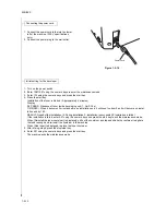
Before installing the key counter, press the Power key on the operation panel to off. Make sure that the Power lamp
is off before turning off the main power switch. And then unplug the power cable from the wall outlet.
Turning off the main power switch before pressing the Power key to off may cause damage to the equipped hard
disk.
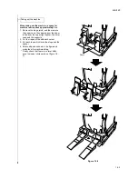
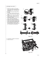
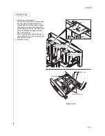
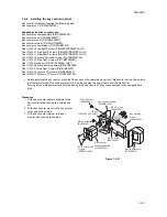
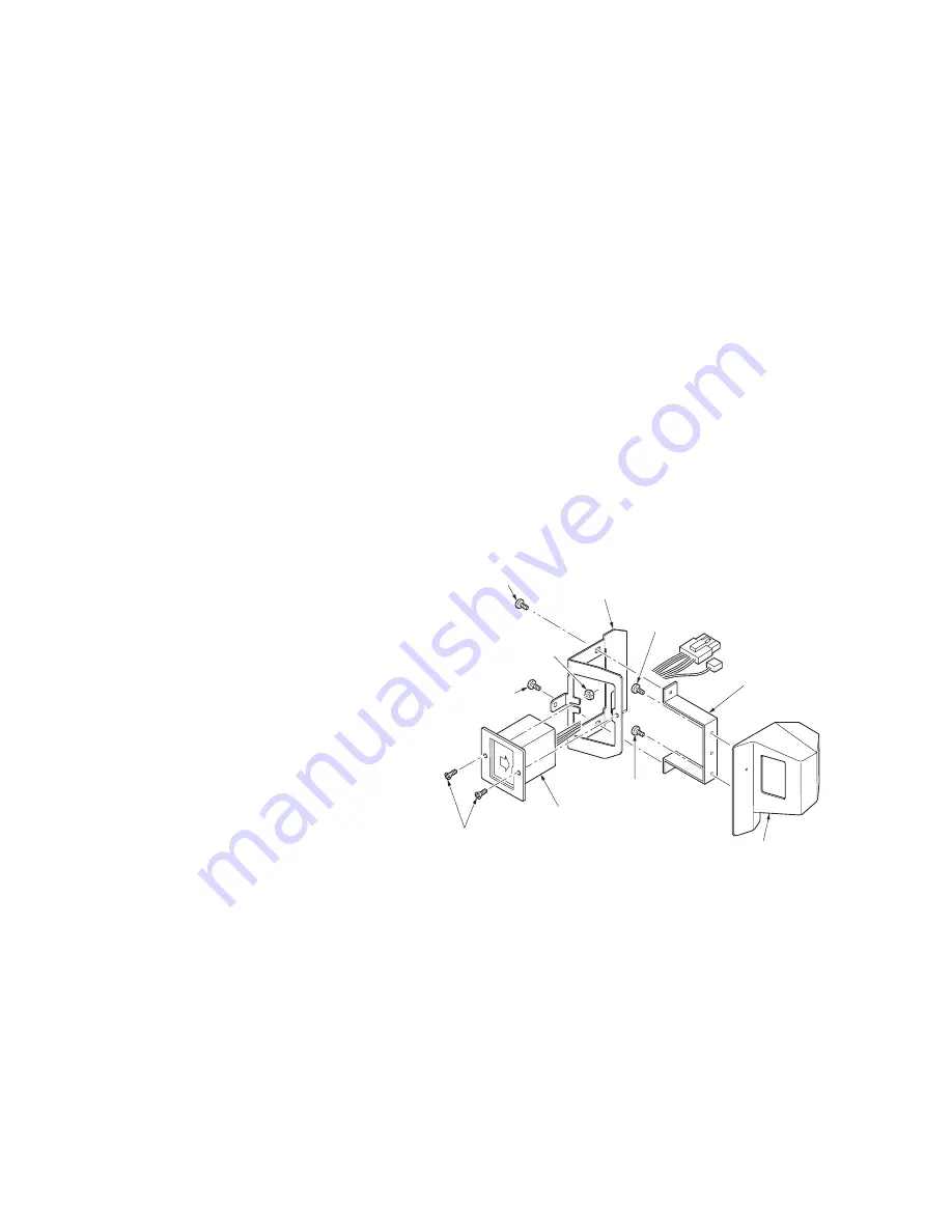
Procedure
1. Fit the key counter socket assembly to the
key counter retainer using two screws and
nut.
2. Fit the key counter mount to the key counter
cover using two screws.
3 Fit the key counter retainer to the key
counter mount using two screws.
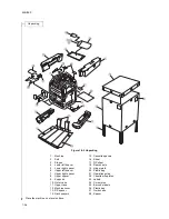
Figure 1-2-21
M3 x 6 flat-head
screws
(7BB003306H)
Key counter
mount
(3066060041)
Key counter cover
(306606001)
M4 x 6 screw
(B4A04060)
M4 x 6 screw
(B4A04060)
Key counter
socket assembly
(3029236241)
M4 x 6 screw
(B4A04060)
M3 nut
(7BC+H01)
Key counter retainer
(302GR03020)
M4 x 6 screw
(B4A04060)
Summary of Contents for TASKalfa 620
Page 1: ...SERVICE MANUAL Published in August 2009 842KP112 2KPSM062 Rev 2 TASKalfa 620 820 ...
Page 4: ...This page is intentionally left blank ...
Page 10: ...This page is intentionally left blank ...
Page 144: ...2KN 2KP 1 3 106 This page is intentionally left blank ...
Page 308: ...2KN 2KP 1 5 88 This page is intentionally left blank ...
Page 412: ...2KN 2KP 2 3 60 This page is intentionally left blank ...
Page 435: ...1 1 INSTALLATION GUIDE INSTALLATION GUIDE FOR SIDE FEEDER ...
Page 442: ...INSTALLATION GUIDE FOR LARGE SIZE SIDE FEEDER ...
Page 460: ...INSTALLATION GUIDE FOR DOCUMENT FINISHER ...
Page 475: ...INSTALLATION GUIDE FOR CENTERFOLD UNIT ...
Page 490: ...INSTALLATION GUIDE FOR MULTI JOB TRAY ...
Page 501: ...INSTALLATION GUIDE FOR PUNCH UNIT ...
Page 512: ...INSTALLATION GUIDE FOR STOPPER GUIDE ...
Page 515: ...INSTALLATION GUIDE FOR PRINTING SYSTEM ...
Page 518: ...INSTALLATION GUIDE FOR SCAN SYSTEM ...
Page 520: ......
Page 521: ......


