


2KN/2KP
1-4-12
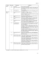
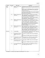
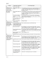
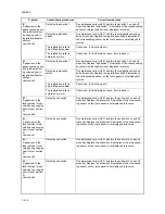
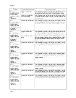
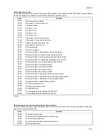
(6)
A paper jam in the
paper feed section is
indicated during
copying (no paper
feed from optional
side feeder).
Jam code 14
Large size side feeder
Defective side feeder feed
switch 1.
Run maintenance item U233 and turn the side feeder feed switch
1 on and off manually. Replace the side feeder feed switch 1 if
indication of the corresponding sensor on the touch panel is not
displayed in reverse.
Defective side feeder feed
switch 2.
Run maintenance item U233 and turn the side feeder feed switch
2 on and off manually. Replace the side feeder feed switch 2 if
indication of the corresponding sensor on the touch panel is not
displayed in reverse.
Check if the side feeder
paper feed motor malfunc-
tions.
Run maintenance item U247 and select the side feeder paper
feed motor on the touch panel to be turned on and off. Check the
status and remedy if necessary.
Electrical problem with the
side feeder paper feed
motor.
Check.
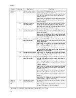
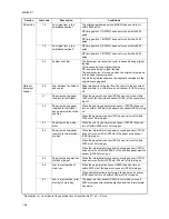
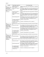
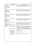
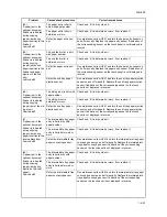
(7)
A paper jam in the
paper feed section is
indicated during
copying (no paper
feed from MP tray).
Jam code 15
Paper on the MP tray is
extremely curled.
Change the paper.
Check if the MP paper feed
pulley, MP forwarding pulley
and MP separation pulley of
the MP tray are deformed.
Check visually and replace any deformed pulleys.
Defective feed switch 1.
Run maintenance item U031 and turn feed switch 1 on and off
manually. Replace feed switch 1 if indication of the corresponding
switch on the touch panel is not displayed in reverse.
Check if the MP feed motor
malfunctions.
Run maintenance item U030 and select the MP feed motor on the
touch panel to be turned on and off. Check the status and remedy
if necessary.
Electrical problem with the
MP feed motor.
Check (see page 1-4-61).
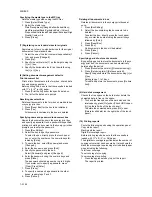
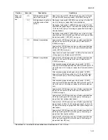
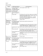
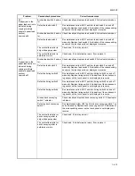
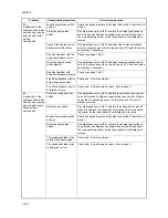
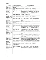
(8)
A paper jam in the
paper feed section is
indicated during
copying (jam in
copier vertical paper
conveying section 1).
Jam code 19
Broken feed switch 4 actua-
tor.
Check visually and replace feed switch 4 if its actuator is broken.
Defective feed switch 4.
Run maintenance item U031 and turn feed switch 4 on and off
manually. Replace feed switch 4 if indication of the corresponding
sensor on the touch panel is not displayed in reverse.
Broken feed switch 5 actua-
tor.
Check visually and replace feed switch 5 if its actuator is broken.
Defective feed switch 5.
Run maintenance item U031 and turn feed switch 5 on and off
manually. Replace feed switch 5 if indication of the corresponding
sensor on the touch panel is not displayed in reverse.
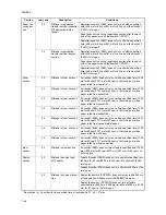
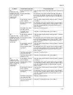
Defective timing switch 3.
Run maintenance item U031 and turn timing switch 3 on and off
manually. Replace timing switch 3 if indication of the correspond-
ing sensor on the touch panel is not displayed in reverse.
Defective timing switch 4.
Run maintenance item U031 and turn timing switch 4 on and off
manually. Replace timing switch 4 if indication of the correspond-
ing sensor on the touch panel is not displayed in reverse.
The vertical feed roller is
dirty with paper powder.
Check and, if it is dirty, clean it.
The vertical feed roller is
deformed or worn.
Check and, if it is deformed or worn, fix or replace it.
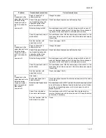
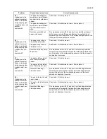
Problem
Causes/check procedures
Corrective measures
Summary of Contents for TASKalfa 620
Page 1: ...SERVICE MANUAL Published in August 2009 842KP112 2KPSM062 Rev 2 TASKalfa 620 820 ...
Page 4: ...This page is intentionally left blank ...
Page 10: ...This page is intentionally left blank ...
Page 144: ...2KN 2KP 1 3 106 This page is intentionally left blank ...
Page 308: ...2KN 2KP 1 5 88 This page is intentionally left blank ...
Page 412: ...2KN 2KP 2 3 60 This page is intentionally left blank ...
Page 435: ...1 1 INSTALLATION GUIDE INSTALLATION GUIDE FOR SIDE FEEDER ...
Page 442: ...INSTALLATION GUIDE FOR LARGE SIZE SIDE FEEDER ...
Page 460: ...INSTALLATION GUIDE FOR DOCUMENT FINISHER ...
Page 475: ...INSTALLATION GUIDE FOR CENTERFOLD UNIT ...
Page 490: ...INSTALLATION GUIDE FOR MULTI JOB TRAY ...
Page 501: ...INSTALLATION GUIDE FOR PUNCH UNIT ...
Page 512: ...INSTALLATION GUIDE FOR STOPPER GUIDE ...
Page 515: ...INSTALLATION GUIDE FOR PRINTING SYSTEM ...
Page 518: ...INSTALLATION GUIDE FOR SCAN SYSTEM ...
Page 520: ......
Page 521: ......


