2KR/2KS-1
1-3-41
U091
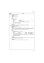
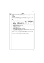
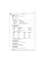
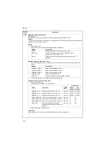
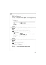
Setting the white line correction
Description
Sets the error detection threshold value for white line correction and displays the count result of abnormal pixels.
Purpose
To perform when replacing the CIS, DP driver PWB or CIS roller.
Method: white line correction
1. Press the start key.
2. Press [EXECUTE].
3. Press the start key. Holding of white reference data is started.
4. The count result of abnormal pixels is displayed.
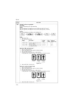
5. Press the system menu key.
6. Place a gray original on the DP with the gray side down. Load paper in the cassette.
The paper should be the same size as the original.
7. Press the start key.
Two test pattern sheets will be printed. (1st sheet: blank sheet, 2nd sheet: Approx. 60 mm black band)
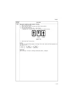
8. If no vertical lines appear on either sheet, the setting has been completed normally.
If vertical black lines appear on the blank sheet and vertical white lines appear in the black band in the
same position, clean the CIS roller and the CIS glass and then repeat white line correction.
If vertical black lines or vertical white lines appear on both sheets, white line correction has been com-
pleted normally. However, the cause of the vertical lines lies in the engine, and thus the engine must be
checked.
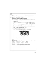
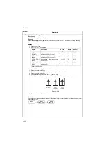
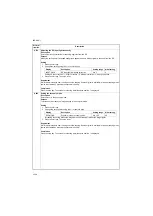
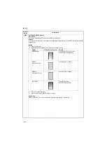
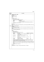
How to view test copies
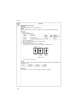
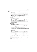
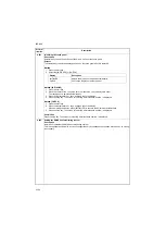
Setting: Threshold value setting
1. Select the item to be set.
2. Change the value using the +/- or numeric keys.
*: Normally the Threshold (Com) value should not be changed from 112, the initial setting.
If white lines appear even though the CIS roller and glass are not dirty, raise the set value.
If fine lines in some originals disappear, lower the set value.
Set within the range 50 to 200. (If set outside this range, the image may be affected.)
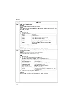
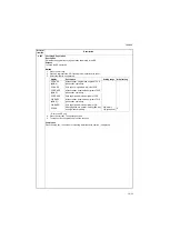
Maintenance
item No.
Description
Display
Description
Calculation(R)
Abnormal pixel count result for color R
Calculation(G)
Abnormal pixel count result for color G
Calculation(B)
Abnormal pixel count result for color B
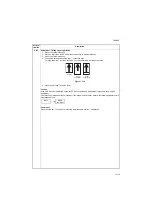
blank sheet
black band
Causes
Corrective measures
No lines
No lines
-
Complete
Black lines
White lines
Dirty CIS roller or CIS
glass
Clean CIS roller or CIS glass and then
perform U091 again
Black lines
No lines
Engine side
U091 ends, check engine
No lines
White lines
Engine side
U091 ends, check engine
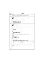
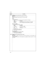
Display
Description
Setting range
Initial setting
Threshold(R)
Displaying of abnormal pixel detection
threshold value for color R
-
-
Threshold(G)
Displaying of abnormal pixel detection
threshold value for color G
-
-
Threshold(Com)*
Setting of abnormal pixel detection thresh-
old value for color
0 to 1023
112
Abnorm Pixel
Threshold
Abnormal pixel threshold value setting
0 to 8191
75
MODE
Switching between white line correction
mode ON/OFF
0: OFF/1: ON/
2: Test mode
0
Summary of Contents for TASKalfa 420i
Page 1: ...SERVICE MANUAL Published in May 2010 842KS113 2KSSM063 Rev 3 TASKalfa 420i TASKalfa 520i ...
Page 4: ...This page is intentionally left blank ...
Page 10: ...This page is intentionally left blank ...
Page 14: ...2KR 2KS This page is intentionally left blank ...
Page 224: ...2KR 2KS 1 4 66 This page is intentionally left blank ...
Page 328: ...2KR 2KS 2 3 30 This page is intentionally left blank ...
Page 371: ...INSTALLATION GUIDE FOR PAPER FEEDER ...
Page 381: ...INSTALLATION GUIDE FOR 3000 SHEETS PAPER FEEDER ...
Page 436: ...INSTALLATION GUIDE FOR CENTER FOLDING UNIT ...
Page 450: ...INSTALLATION GUIDE FOR MAILBOX ...
Page 458: ...INSTALLATION GUIDE FOR HOLE PUNCH UNIT ...
Page 470: ...INSTALLATION GUIDE FOR BUILT IN FINISHER ...
Page 483: ...INSTALLATION GUIDE FOR JOB SEPARATOR ...
Page 491: ...INSTALLATION GUIDE FOR FAX System ...
Page 507: ......
Page 508: ......

