2KR/2KS
1-5-21
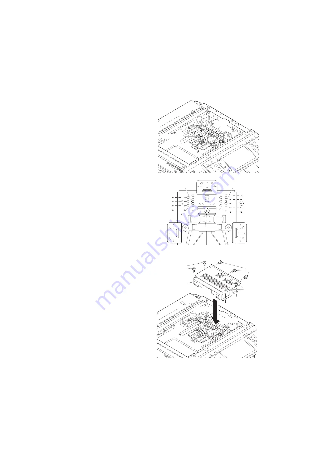
Refitting the ISU
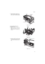
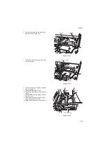
5. Adjust the position of ISU to the frame hole
of number and the same number which are
recorded in the lens of ISU and then insert
two positioning pins.
Example: When a lens number is 5, move
ISU so that the positioning hole of 5 of the
number stamped in the scanner unit suit and
insert two pins.
6. Remove two positioning pins after fixing ISU
with three screws.
Figure 1-5-41
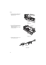
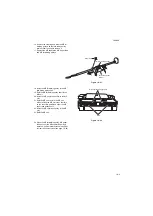
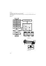
7. Refit two connectors.
8. Refit the ISU cover.
Screw tightening order
1) Three screws A
2) Four screws B
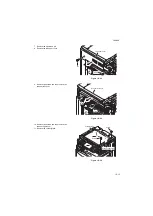
9. Refit the contact glass.
Figure 1-5-42
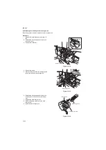
ISU
Positioning pins
Positioning hole
Positioning hole
Lens number
Connector
Connector
ISU cover
Screws A
Screws B
Screws B
Summary of Contents for TASKalfa 420i
Page 1: ...SERVICE MANUAL Published in May 2010 842KS113 2KSSM063 Rev 3 TASKalfa 420i TASKalfa 520i ...
Page 4: ...This page is intentionally left blank ...
Page 10: ...This page is intentionally left blank ...
Page 14: ...2KR 2KS This page is intentionally left blank ...
Page 224: ...2KR 2KS 1 4 66 This page is intentionally left blank ...
Page 328: ...2KR 2KS 2 3 30 This page is intentionally left blank ...
Page 371: ...INSTALLATION GUIDE FOR PAPER FEEDER ...
Page 381: ...INSTALLATION GUIDE FOR 3000 SHEETS PAPER FEEDER ...
Page 436: ...INSTALLATION GUIDE FOR CENTER FOLDING UNIT ...
Page 450: ...INSTALLATION GUIDE FOR MAILBOX ...
Page 458: ...INSTALLATION GUIDE FOR HOLE PUNCH UNIT ...
Page 470: ...INSTALLATION GUIDE FOR BUILT IN FINISHER ...
Page 483: ...INSTALLATION GUIDE FOR JOB SEPARATOR ...
Page 491: ...INSTALLATION GUIDE FOR FAX System ...
Page 507: ......
Page 508: ......

