background image

7

I

D

11

11

9

9

R

2

8

9

10

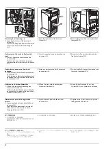
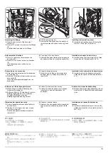
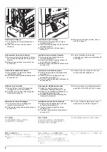
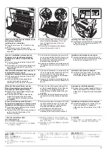
[When installing the document finisher to the 
monochrome machine]
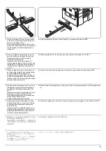
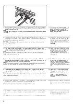
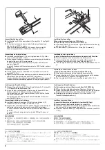
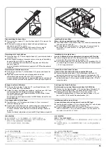
Installing the curl eliminator
15.

Open the eject cover (8) of the MFP or the 
printer.

16.

Remove two screws (9) securing the 
feedshift guide assembly (10) to remove the 
assembly.

17.

Fit the curl eliminator (R) to the eject cover 
(8) such that the projections (11) on the 
cover fit into the two ends of the curl 
eliminator (R).

18.

Secure the curl eliminator (R) using two 
screws (9) removed in step 16.

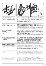
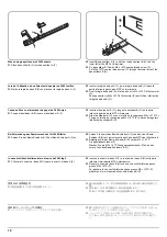
Installing the connecting plate
19.

Install the connecting plate (D) to the left side 
of the MFP or the printer using two M4 × 10 
tap Tight S Screws (I).

[Lors de l’installation du retoucheur de 
document sur la machine monochrome]
Installation de l’élément d’élimination des 
boucles
15.

Ouvrir le couvercle d’éjection (8) de la MFP 
ou de l’imprimante.

16.

Retirer deux vis (9) fixant l’assemblage de la 
glissière d’alimentation (10) pour retirer 
l’assemblage.

17.

Fixer l’élément d’élimination des boucles (R) 
sur le couvercle d’éjection (8) de façon à ce 
que les saillies (11) du couvercle s’insèrent 
dans les deux extrémités de l’élément 
d’élimination des boucles (R).

18.

Asegure el eliminador de curvatura del papel 
(R) utilizando dos tornillos (9) quitados en el 
paso 16.

Installation de la plaque de connexion
19.

Installer la plaque de connexion (D) sur le 
côté gauche du MFP ou imprimante à l’aide 
de deux vis S taraudées M4 × 10 (I).

[Cuando instale el finalizador de documentos en 
una máquina de blanco y negro]
Instalación del eliminador de curvatura del papel 
15.

Abra la cubierta de expulsión (8) de la MFP 
o de la impresora.

16.

Quite dos tornillos (9) que aseguran el 
conjunto de la guía de cambio de 
alimentación (10) para quitar el conjunto.

17.

Coloque el eliminador de curvatura del papel 
(R) en la cubierta de expulsión (8) de forma 
que los resaltos (11) de la cubierta se 
coloquen en los dos extremos del eliminador 
de curvatura del papel (R).

18.

Asegure el eliminador de curvatura del papel 
(R) utilizando dos tornillos (9) quitados en el 
paso 16.

Instalación de la placa de conexión 
19.

Instale la placa de conexión (D) en el lado 
izquierdo de la MFP o impresora utilizando 
dos tornillos de ajuste M4 × 10 (I).

[Wenn der Dokument-Finisher auf der 
Monochrommaschine angebracht wird]
Anbringen der Glättungseinrichtung
15.

Öffnen Sie die Auswurfabdeckung (8) des 
MFP oder des Druckers.

16.

Entfernen Sie die beiden Schrauben (9), 
welche die Papiervorschub-Umschalt-
Führungseinheit (10) befestigt, um diese 
auszubauen.

17.

Setzen Sie die Glättungseinrichtung (R) so 
auf die Auswurfabdeckung (8) auf, dass die 
Vorsprünge (11) der Abdeckung in die 
beiden Enden der Glättungseinrichtung (R) 
eingreifen.

18.

Befestigen Sie die Glättungseinrichtung (R) 
mit den im Schritt 16 entfernten Schrauben 
(9).

Anbringen der Verbindungsplatte
19.

Bringen Sie die Verbindungsplatte (D)auf der 
linken Seite des MFP oder Drucker mit den 
beiden M4 × 10 Passstift-Verbundschrauben 
(I) an.

[In caso di installazione della finitrice di 
documenti in un apparecchio in bianco e nero]
Installazione dell’eliminatore di arricciature
15.

Aprire la copertura dell’uscita carta (8) della 
MFP o dello stampatore.

16.

Togliere le due viti (9) che fissano il gruppo di 
guida di cambio alimentazione (10) e 
rimuovere il gruppo.

17.

Montare l’eliminatore di arricciature (R) nella 
copertura dell’uscita carta (8) in modo tale 
che le parti sporgenti (11) sulla copertura 
siano inserite nelle due estremità 
dell’eliminatore di arricciature (R).

18.

Fissare l’eliminatore di arricciature (R) 

utilizzando le due viti (9) rimosse al punto 16. 

Installazione della piastra di connessione
19.

Installare la piastra di connessione (D) sul 
lato destro della MFP o stampatore 
utilizzando due viti con testa a croce S M4 × 
10 (I).

[ モノクロ機へドキュメントフィニッシャを
設置する場合 ]
デカーラーの取り付け

15.

MFP 本体またはプリンタ本体の排出カバー
(8) を開く。

16.

ビス (9)2 本を外し、分岐ガイド組立 (10) を
取り外す。

17.

デカーラ (R) の両端に半押し (11) がはまる
位置で、デカーラ (R) を排出カバー(8) に取
り付ける。

18.

手順 16 で外したビス (9)2 本でデカーラ (R)
を固定する。

連結板の取り付け

19.

MFP 本体またはプリンタ本体の左側にビス
M4 × 10 タップタイト S (I)2 本で連結板
(D) を取り付ける。

[ 将装订器安装至黑白机器时 ]
安装防纸张卷曲装置

15.

打开 MFP 或打印机的出纸盖板(8)。

16.

拆下固定供纸换向导板组件(10)的 2 颗螺丝

(9)以便拆下该组件。

17.

将防纸张卷曲装置(R)固定在出纸盖板(8)
上,使盖板上的突出部(11)嵌入防纸张卷曲
装置(R)的两端。

18.

使用步骤 16 中拆下的 2 颗螺丝(9)固定防纸
张卷曲装置(R)。

安装连接板

19.

使用 2 颗 M4 × 10 攻丝紧固型 S 螺丝(I)将
连接板(D)安装至 MFP 或打印机的左侧。

Summary of Contents for TASKalfa 420i

Page 1: ...SERVICE MANUAL Published in May 2010 842KS113 2KSSM063 Rev 3 TASKalfa 420i TASKalfa 520i ...

Page 2: ...icials for details in your area for proper disposal ATTENTION IL Y A UN RISQUE D EXPLOSION SI LA BATTERIE EST REMPLACEE PAR UN MODELE DE TYPE INCORRECT METTRE AU REBUT LES BATTERIES UTILISEES SELON LES INSTRUC TIONS DONNEES Il peut être illégal de jeter les batteries dans des eaux d égout municipales Vérifiez avec les fonc tionnaires municipaux de votre région pour les détails concernant des déche...

Page 3: ... 3 38 1 3 41 to 1 3 43 1 3 58 1 3 59 1 3 60 1 3 74 1 3 81 1 3 84 1 3 94 to 1 3 97 1 3 100 1 3 101 1 4 3 1 4 4 1 4 8 1 5 24 1 5 25 1 5 28 1 6 1 2 3 6 2 3 7 2 3 15 to 2 3 17 2 4 1 2 4 3 to 2 4 6 2 February 4 2010 1 2 4 1 2 11 1 3 2 1 3 3 1 3 5 1 3 25 1 3 26 1 3 50 to 1 3 53 1 3 74 1 3 95 1 4 8 1 4 11 2 1 11 3 May 7 2010 1 1 1 ...

Page 4: ...This page is intentionally left blank ...

Page 5: ...rsonnel to ensure the safety of their customers their machines as well as themselves during maintenance activities Service personnel are advised to read this booklet carefully to familiarize themselves with the warnings and precautions described here before engaging in maintenance activities ...

Page 6: ... this symbol CAUTION Bodily injury or damage to property may result from insufficient attention to or incorrect compliance with warning messages using this symbol Symbols The triangle symbol indicates a warning including danger and caution The specific point of attention is shown inside the symbol General warning Warning of risk of electric shock Warning of high temperature indicates a prohibited ...

Page 7: ... or dusty place This may cause fire or electric shock Do not install the copier near a radiator heater other heat source or near flammable material This may cause fire Allow sufficient space around the copier to allow the ventilation grills to keep the machine as cool as possible Insufficient ventilation may cause heat buildup and poor copying performance Always handle the machine by the correct l...

Page 8: ... carefully Always check that the copier is correctly connected to an outlet with a ground connection Check that the power cable covering is free of damage Check that the power plug is dust free If it is dirty clean it to remove the risk of fire or electric shock Never attempt to disassemble the optical unit in machines using lasers Leaking laser light may damage eyesight Handle the charger section...

Page 9: ...r trapped wire and missing screws Check that all the caution labels that should be present on the machine according to the instruction handbook are clean and not peeling Replace with new ones if necessary Handle greases and solvents with care by following the instructions below Use only a small amount of solvent at a time being careful not to spill Wipe spills off completely Ventilate the room wel...

Page 10: ...This page is intentionally left blank ...

Page 11: ...tion Address Book Adding One Touch Keys 1 3 114 11 Internet Browser Setup 1 3 115 12 Applications 1 3 116 13 System Settings 1 3 116 14 User Login Administration 1 3 118 15 Job accounting 1 3 119 1 4 Troubleshooting 1 4 1 Paper misfeed detection 1 4 1 1 Paper misfeed indication 1 4 1 2 Paper misfeed detection conditions 1 4 2 3 Paper misfeeds 1 4 12 1 4 2 Self diagnosis 1 4 24 1 Self diagnostic fu...

Page 12: ...24 1 5 4 Drum section 1 5 25 1 Detaching and refitting the drum unit 1 5 25 2 Detaching and refitting the main charger unit 1 5 26 3 Detaching and refitting the drum separation claws 1 5 27 1 5 5 Developing section 1 5 28 1 Detaching and refitting the developing unit 1 5 28 1 5 6 Transfer section 1 5 29 1 Detaching and refitting the transfer roller unit 1 5 29 1 5 7 Fuser section 1 5 30 1 Detachin...

Page 13: ...5 4 Others 2 2 6 2 3 Operation of the PWBs 2 3 1 Power source PWB 2 3 1 2 3 2 Engine PWB 2 3 5 2 3 3 Main PWB 2 3 14 2 3 4 ISM PWB 2 3 23 2 3 5 Main operation PWB 2 3 26 2 4 Appendixes Maintenance parts list 2 4 1 Maintenance kits 2 4 2 Periodic maintenance procedures 2 4 3 Chart of image adjustment procedures 2 4 7 Wiring diagram No 1 2 4 9 Wiring diagram No 2 2 4 10 Wiring diagram No 3 2 4 11 Wi...

Page 14: ...2KR 2KS This page is intentionally left blank ...

Page 15: ...mercial 9 Envelope 6 Commercial 6 3 4 Monarch ISO B5 Youkei 2 Youkei 4 Zoom level Manual mode 25 to 400 1 increments Auto mode Preset zoom Printing speed 42 ppm model A4 Letter 42 sheets min A4R LetterR 27 sheets min A3 Ledger 23 sheets min B4 Legal 23 sheets min B5 42 sheets min B5R 22 sheets min A5R 16 sheets min 52 ppm model A4 Letter 52 sheets min A4R LetterR 31 sheets min A3 Ledger 26 sheets ...

Page 16: ... 1500 lux maximum Dimensions 599 W x 646 D x 745 H mm main unit only 23 9 16 W x 25 7 16 D x 29 5 16 H main unit only Weight 85 kg 187 lbs Space required 753 W x 646 D mm using MP tray 29 5 8 W x 25 7 16 D using MP tray Power source 120 V AC 60 Hz 12 A 220 to 240 V AC 50 Hz 6 3 A Options Document processor paper feeder 3000 sheet paper feeder document finisher 3000 sheet document finisher centerfo...

Page 17: ...format TIFF MMR JPEG compression JPEG XPS PDF MMR JPEG compression PDF high compression Scanning speed A4 600 dpi Image quality Text Photo original B W Single scanning 52 images min Interface Ethernet 10 BASE T 100 BASE TX Network protocol TCP IP Transmission system PC transmission SMB Scan to SMB FTP Scan to FTP FTP over SSL E mail transmission SMTP Scan to E mail Twain scan WIA scan NOTE These s...

Page 18: ...5 6 7 8 9 10 1 Original cover option 2 Original size indicator plates 3 Clip holder 4 Slit glass 5 Attention indicator 6 Receive indicator 7 Left cover 1 8 Left cover 1 lever 9 Left cover 2 10 Left cover 2 handle 11 Contact glass 12 Operation panel 13 Cassette 1 14 Cassette 2 ...

Page 19: ...2KR 2KS 1 1 5 Figure 1 1 2 15 16 17 18 20 19 15 Toner container stopper 16 Toner container 17 Waste toner box 18 Paper feed unit A2 19 Paper feed unit cover A3 20 Knob ...

Page 20: ...ot A1 22 Front cover 23 Paper width adjusting tab 24 Paper length guide 25 Top tray 26 Main power switch 27 Paper width guide 28 MP tray multi purpose tray 29 Optional interface slot OPT2 30 USB memory slot A2 31 USB interface connector B1 32 Network interface connector 33 Optional interface slot OPT1 ...

Page 21: ...7 Memory indicator 8 Attention indicator 9 Interrupt key indicator 10 Logout key indicator 11 Power key indicator 12 Main power indicator 13 Status Job cancel key indicator 14 Program key indicator 15 Application key indicator 16 Document box key indicator 17 Accessibility key indicator 18 Send key indicator 19 Copy key indicator 20 Numeric keys 21 Clear key 22 Quick No search key 23 Enter key 24 ...

Page 22: ...th 1 4 2 3 5 6 7 11 8 10 9 1 Cassette paper feed section 2 MP tray paper feed section 3 Image scanner section 4 Laser scanner section 5 Drum section 6 Developing section 7 Toner container section 8 Transfer and separation sections 9 Fuser section 10 Eject and switchback sections 11 Duplex section ...

Page 23: ...erature and cool or hot direct air Avoid places subject to dust and vibrations Choose a surface capable of supporting the weight of the machine Place the machine on a level surface maximum allowance inclination 1 Avoid air borne substances that may adversely affect the machine or degrade the photoconductor such as mer cury acidic of alkaline vapors inorganic gasses NOx SOx gases and chlorine based...

Page 24: ...rd Installing toner Install the optional original cover or the DP Install other optional devices Print out the user setting list Make test copies Output an own status report maintenance item U000 Attaching the language label 230 V specifications only Exit maintenance mode Start Load paper Install the waste toner box Setting the delivery date maintenance item U278 Release of cassette lift plate Com...

Page 25: ...2KR 2KS 1 2 3 Moving the machine When moving the machine pull out the four handles on the right and left sides and hold them Figure 1 2 2 B1 A2 DP OPT 1 Handle Handle Handle Handle ...

Page 26: ...19 18 18 11 18 18 18 18 2 3 4 5 9 6 1 Machine 2 Outer case 3 Inner frame 4 Skid 5 Bottom left pad 6 Bottom right pad 7 Upper left pad 8 Upper right pad 9 Sheets 10 Machine cover 11 Document tray 12 Power cord 13 Plastic bag 14 Operation guide 15 Paper size plates 16 Plastic bag 17 Cursor pins 18 Hinge joints 19 Bar code labels ...

Page 27: ... using a level gauge and adjust the level bolts at the bottom of the machine to optimize levelness 1 Turn the lever of the machine rear side with the tool to release the lever holding the mir ror 1 and 2 frames Figure 1 2 5 Remove the tapes and pad B1 A2 DP OP T1 Pad Tape Tape Install the optional paper feeder Release the lever holding mirror 1 and 2 frames Lever ...

Page 28: ... Figure 1 2 6 1 Pull the cassette out 2 Holding the paper width adjusting tab both ends move the paper width guides to fit the paper size Figure 1 2 7 3 Adjust the length adjustment plate to fit the paper size Figure 1 2 8 Release of cassette lift plate Lift plate stopper Lift plate stopper Cassette Load paper Paper width guide Paper width guide Paper width adjusting tab Length adjustment plate ...

Page 29: ...te Figure 1 2 9 1 Open the front cover 2 Tap the top of the toner container five to six times Figure 1 2 10 3 Shake the toner container approximately 10 times in the horizontal direction to stir toner Figure 1 2 11 Install the toner container Toner container Toner container ...

Page 30: ...er Figure 1 2 13 1 Install the optional original cover or DP 1 Install the optional devices job separator built in finisher document finisher and or fax kit etc as necessary 1 Connect the power cord to the connector on the machine 2 Insert the power plug into the wall outlet Toner container Install the waste toner box Waste toner box Install the optional original cover or the DP Install other opti...

Page 31: ...and press the start key 2 Select MAINTENANCE and press the start key to output a list of the current settings of the maintenance items 3 Press the stop key 1 Enter 001 using the numeric keys and press the start key The machine exits the maintenance mode 1 Select Report Print to output the user various setting reports 1 Place an original and make test copies 1 According to need attach the correspon...

Page 32: ...hing between double and single counts DOUBLE COUNT A3 LEDGER U260 Selecting the timing for copy counting After ejection U285 Setting service status page ON U326 Setting the black line cleaning indication ON 8 U328 Side ejection setting OFF U342 Setting the ejection restriction ON U343 Switching between duplex simplex copy mode OFF ...

Page 33: ...55 H01 One 1 M3 8 bronze binding screw P N B1B03080 One 1 M4 30 tap tight S screw P N B1B54300 Five 5 M4 6 chrome TP screws P N B4A04060 Two 2 M4 10 chrome TP screws P N B4A04100 Procedure 1 Press the power key on the operation panel to off Make sure that the main power indica tor and the memory indicator are off before turning off the main power switch And then unplug the power cable from the wal...

Page 34: ...r 6 Remove ten screws and then remove the rear cover Figure 1 2 15 7 Remove two screws and then remove the scanner right cover Figure 1 2 16 B1 A2 DP OP T1 Rear cover Screws ISU filter cover Screws Screws Screw DP Screw Screw Scanner right cover ...

Page 35: ...t the aperture plate on the right upper cover using nippers Figure 1 2 17 10 Release the wire saddle and then stretch the key counter wire 11 Close the wire saddle Figure 1 2 18 B1 A2 DP OPT 1 Right upper cover Aperture Screw Screw Screw D Key counter wire Wire saddle Key counter wire ...

Page 36: ...the key counter cover retainer 15 Insert the hook of the key counter cover retainer in the slit of the right upper cover 16 Fit the key counter cover retainer to the machine using the M4 x 20 screw 17 Refit the scanner right cover Figure 1 2 20 B1 A2 DP OPT Upper right cover Aperture Key counter wire A2 DP M4 x 20 screw 7BB100420H Key counter cover retainer 302GR03010 Right upper cover Slit Key co...

Page 37: ...cket assembly Figure 1 2 21 21 Turn the main power switch on and enter the maintenance mode 22 Run maintenance item U204 and select KEY COUNTER 23 Exit the maintenance mode 24 Check that the message requesting the key counter to be inserted is displayed on the touch panel when the key counter is pulled out 25 Check that the counter counts up as prints are made B1 A2 DP OPT1 Key counter wire M4 x 6...

Page 38: ... remove the main PWB lid 3 Open clamps on both ends of the memory socket on the main PWB 4 Remove the expanded memory 5 Insert the expanded memory into the mem ory socket so that the notch on the memory align with the corresponding protrusion in the slot The memory module is secured to the mem ory socket with the clamps 6 Refit the main PWB lid 7 Print a status page to check the expanded memory Se...

Page 39: ...numeric keys Enter 001 using the cursor up down keys or numeric keys and press the start key Enter the maintenance item number using the cursor up down keys or numeric keys The selected maintenance item is run Press the stop key Press the start key Start End Maintenance mode is entered The maintenance item is selected Maintenance mode is exited Repeat the same maintenance item Run another maintena...

Page 40: ...eflection in the paper 0 0 0 0 U053 Setting the adjustment of the motor speed Drive motor Eject motor Polygon motor Paper feed motor 0 0 0 0 U059 Setting fan mode MODE1 Optical U061 Turning the exposure lamp on U063 Adjusting the shading position 0 U065 Adjusting the scanner magnification Main scanning direction Auxiliary scanning direction 0 0 U066 Adjusting the scanner leading edge registration ...

Page 41: ...near end mode OFF U139 Displaying the temperature and humidity U144 Setting toner disposal operation MODE2 U155 Checking sensors for toner U157 Checking the developing drive time U158 Checking the developing count Fuser and cleaning U161 Setting the fuser control temperature Driving start temperature when warm up starts Control temperature for displaying Ready for copying Control temperature durin...

Page 42: ... destination U253 Switching between double and single counts DOUBLE COUNT A3 LEDGER 1 U260 Selecting the timing for copy counting After ejection 1 U265 Setting OEM purchaser code U278 Setting the delivery date U285 Setting service status page ON U326 Setting the black line cleaning indication ON 8 1 U328 Side ejection setting OFF 1 U332 Setting the size conversion factor 1 0 1 U341 Specific paper ...

Page 43: ...l operation control U908 Checking the total counter value U910 Clearing the black ratio data U911 Checking copy counts by paper sizes U917 Setting backup data reading writing U920 Checking the copy counts U927 Clearing the all copy counts and machine life counts one time only U928 Checking machine life counts U931 Setting the automatic toner install OFF U935 Relay board maintenance MODE0 1 U942 Se...

Page 44: ...d location When output is complete the screen for selecting an item is displayed The output status is displayed Method Send to the USB memory 1 Press the power key on the operation panel and after verifying the main power indicator has gone off switch off the main power switch 2 Insert USB memory in USB memory slot 3 Turn the main power switch on 4 Enter the maintenance item 5 Press the start key ...

Page 45: ...70 001 C8140 001 C8170 001 C8180 001 M00 01 M00 01 16 15 14 13 12 11 10 9 8 7 6 5 4 3 2 1 Count 1876543 166554 4988 4988 4988 4988 1103 1103 1103 1103 1027 1027 1027 1027 406 36 Event Descriprions 10 01 08 01 01 10 01 08 01 02 10 01 08 01 01 10 01 08 01 02 10 01 08 01 01 10 01 08 01 02 10 01 08 01 01 10 01 08 01 01 12 03 08 01 01 12 03 08 01 01 12 03 08 01 01 12 03 0A 01 01 12 03 08 01 01 12 03 08...

Page 46: ...er feeder vertical paper conveying section 20 Misfeed in MP tray vertical paper conveying section 21 Multiple sheets in paper feed section 22 Multiple sheets in vertical conveying section 23 Multiple sheets in MP tray conveying section 30 Misfeed in registration transfer section 40 Misfeed in fuser section MP tray 41 Misfeed in fuser section cassette 1 42 Misfeed in fuser section cassette 2 43 Mis...

Page 47: ...er and machine built in finisher b Detail of paper source Hexadecimal 00 MP tray 01 Cassette 1 02 Cassette 2 03 Cassette 3 paper feeder 04 Cassette 4 paper feeder 08 3000 sheet paper feeder 05 06 07 09 Reserved c Detail of paper size Hexadecimal 01 Monarch 02 Business 03 International DL 04 International C5 05 Executive 06 Letter R 86 Letter E 07 Legal 08 A4R 88 A4E 09 B5R 89 B5E 0A A3 0B B4 0C Le...

Page 48: ...Mailbox tray 6 FD 3E Mailbox tray 6 FU 47 Mailbox tray 7 FD 48 Mailbox tray 7 FU 4 Service Call Log Count Service Code Remembers 1 to 8 of occurrence of self diag nostics error If the occurrence of the previ ous diagnostics error is less than 8 all of the diagnostics errors are logged The total page count at the time of the self diagnostics error Self diagnostic error code See page 1 4 26 Example ...

Page 49: ... 7 Counter Log Comprised of three log counters includ ing paper jams self diagnostics errors and replacement of the toner container f Paper jam g Self diagnostic error h Maintenance item replacing Indicates the log counter of paper jams depending on location Refer to Paper Jam Log All instances including those are not occurred are displayed Indicates the log counter of self diagnos tics errors dep...

Page 50: ... Security Kit Data Security Kit E Software Type II Installed Cassette 3000 Finisher Not Installed Installed FAX Information Slot1 Slot2 Rings Normal Rings FAX TEL Rings TAD Option DIMM Size 3 3 3 16 MB Digital Dot Coverage Average Total K 1 10 Copy K 1 10 Printer K 1 10 FAX K 1 10 Period Last Page Usage Page A4 Letter Conversion 1111111 11 1111111 11 1111111 11 1111111 11 03 11 2009 27 10 2009 08 ...

Page 51: ...0 0 0 0 0 0 0 0000000 0000000 0000000 0000000 0000000 0000000 0000000 0000000 0000000 0000000 F00 U00 0 0 0 30 30 70 70 abcde 1 0000 0000 0000 0000 0000 0000 0000 0000 0000 0000 0000 0000 0000 0000 0000 0000 0000 0000 0000 0000 0000 0000 0000 0000 0000 12345678 11223344 00001234abcd567800001234abcd5678 01234567890123456789012345678901 0008 00 07 XXXXXXXX 0000000000 F80C001A37 302A183C00 000100013D...

Page 52: ...isher Not Installed 13 Presence or absence of the optional mailbox Installed Not Installed 14 Presence or absence of the optional job separator Installed Not Installed 15 Presence or absence of the optional data security kit Installed Not Installed 16 Page of relation to the A4 Letter 17 Average coverage for total 18 Average coverage for copy 19 Average coverage for printer 20 Average coverage for...

Page 53: ...gin 38 Margin Page length Page width settings Top margin integer part Top margin decimal part Left margin integer part Left margin decimal part Page length integer part Page length decimal part Page width integer part Page width decimal part 39 Life counter The first line Machine life counter MP tray counter Cassette 1 counter Cassette 2 counter Cassette 3 counter Cassette 4 counter Duplex counter...

Page 54: ...wer switch off and on An error code is displayed in case of an initialization error Refer to the table of the error codes on P 1 3 19 When ERROR 09 occurred turn main power switch off then on format the hard disk using maintenance item U024 and execute initialization using maintenance item U002 For other errors occurred turn main power switch off then on and execute initialization using maintenanc...

Page 55: ...ayed U004 Displaying the machine number Description Sets or displays the machine number Purpose To check or set the machine number Method 1 Press the start key If the machine serial number of engine PWB matches with that of main PWB If the machine serial number of engine PWB does not match with that of main PWB Setting Carry out if the machine serial number does not match 1 Press EXECUTE 2 Press t...

Page 56: ...NGUAGE Optional language ROM DICTIONARY DBA Database connection Solution Framework Solution framework DP Optional DP ROM 500x2PF Optional paper feeder ROM 3000PF Optional 3000 sheet paper feeder ROM 1000DF Optional document finisher ROM 3000DF MAIN Optional 3000 sheet document finisher main ROM 3000DF MIDDLE Optional 3000 sheet document finisher Inner tray ROM MAIL BOX Optional mailbox ROM BOOKLET...

Page 57: ...aintenance item U021 Error codes U024 HDD formatting Description Initializes the HDD In addition the following settings are also initialized by initializing the HDD System menu user login administration job accounting address book one touch keys and document box etc shortcuts and panel programs Initializing the HDD will cause installed applications to be deleted Reinstall applications as necessary...

Page 58: ...t key 2 Turn each switch on and off manually to check the status When a switch is detected to be in the ON position the display for that switch will be highlighted Optional Completion Press the stop key The screen for selecting a maintenance item No is displayed Maintenance item No Description Display Operation MAIN Drive motor DM is turned ON FEED Paper feed motor PFM is turned ON EJECT FW Eject ...

Page 59: ... operated 3 Press the start key The solenoid turns on for 1 s Optional 4 To stop motor driving press MOTOR ON again Completion Press the stop key The screen for selecting a maintenance item No is displayed Maintenance item No Description Display Clutches PF1 Paper feed clutch 1 PFCL1 PF2 Paper feed clutch 2 PFCL2 PF MP TRAY MP paper feed clutch MPPFCL FEED1 Feed clutch 1 FCL1 FEED2 Feed clutch 2 F...

Page 60: ...start key The value is set Remark When changing the setting value of Large each item is modified equal to amount of the value which is changed adds also the value of Small each item and is pulled Maintenance item No Description Display Description LSU OUT TOP Leading edge registration adjustment LSU OUT LEFT Center line adjustment Display Description Setting range Initial setting Change in value p...

Page 61: ... from the MP tray is changed the difference from the former value is added to or subtracted from the values of other items Maintenance item No Description U034 U066 P 1 3 29 U071 P 1 3 34 Display Description Setting range Initial setting Change in value per step LSUOUT LEFT MPT Paper feed from MP tray 10 0 to 10 0 0 0 1 mm LSUOUT LEFT CAS 1 Paper feed from cassette 1 10 0 to 10 0 0 0 1 mm LSUOUT L...

Page 62: ...es the fan motors Description To check the operation of the fan motors Method 1 Press the start key 2 Select the fan motor to be operated 3 Press the start key The operation starts 4 To stop operation press the stop key Completion Press the stop key The screen for selecting a maintenance item No is displayed Maintenance item No Description U034 U067 P 1 3 30 U072 P 1 3 36 Display Setting Setting r...

Page 63: ...Press the stop key The indication for selecting a maintenance item No appears U053 Setting the adjustment of the motor speed Description Performs fine adjustment of the speeds of the motors Purpose To adjust the speed of the respective motors when the magnification is not correct Method 1 Press the start key 2 Select the item to be adjusted Maintenance item No Description Display Description Setti...

Page 64: ...mpletion Press the stop key The indication for selecting a maintenance item No appears U059 Setting fan mode Description Specifies mode for paper conveying fan motors during conveying paper Purpose To prevent contamination caused by paper conveying fan motors scattering toner select MODE2 Setting 1 Press the start key 2 Select the mode Initial setting MODE1 3 Press the start key The setting is set...

Page 65: ...e changed so that shading is possible without being affected by the flaws or stains Method 1 Press the start key 2 Change the setting using the or numeric keys Increasing the setting moves the shading position toward the machine left and decreasing it moves the position toward the machine right 3 Press the start key The value is set Supplement While this maintenance item is being executed copying ...

Page 66: ...r copy example 2 decrease the value Figure 1 3 8 5 Press the start key The value is set Adjustment Auxiliary scanning direction 1 Press the system menu key 2 Place an original and press the start key to make a test copy 3 Press the system menu key 4 Change the setting value using the or numeric keys For copy example 1 increase the value For copy example 2 decrease the value Figure 1 3 9 5 Press th...

Page 67: ...he setting value using the or numeric keys For copy example 1 increase the value For copy example 2 decrease the value Figure 1 3 10 7 Press the start key The value is set Caution Check the copy image after the adjustment If the image is still incorrect perform the following adjustments in maintenance mode Completion Press the stop key The screen for selecting a maintenance item No is displayed Ma...

Page 68: ... For copy example 1 increase the value For copy example 2 decrease the value Figure 1 3 11 7 Press the start key The value is set Caution Check the copy image after the adjustment If the image is still incorrect perform the following adjustments in maintenance mode Completion Press the stop key The screen for selecting a maintenance item No is displayed Maintenance item No Description Display Desc...

Page 69: ...ased 4 Press the start key The value is set 5 Select BLACK LINE of the screen for selecting an item 6 Select the scanning position using the or numeric keys 7 Press the start key The value is set 8 Set the original the one which density is known in the DP and press the system menu key The screen for the test copy mode is displayed 9 Press the start key Test copy is executed 10 Perform the test cop...

Page 70: ... value For copy example 2 decrease the value Figure 1 3 12 5 Press the start key The value is set Caution Check the copy image after the adjustment If the image is still incorrect perform the following adjustments in maintenance mode Maintenance item No Description Display Description Setting range Initial setting Change in value per step MOTOR ADJ FRONT Magnification in the auxiliary scanning dir...

Page 71: ...or copy example 1 increase the value For copy example 2 decrease the value Figure 1 3 13 5 Press the start key The value is set Caution Check the copy image after the adjustment If the image is still incorrect perform the following adjustments in maintenance mode Completion Press the stop key The screen for selecting a maintenance item No is displayed Maintenance item No Description Original Copy ...

Page 72: ...rt key The value is set Caution If the CCD first side is adjusted check the CCD second side and if adjustment is required carry out the adjustment Check the copy image after the adjustment If the image is still incorrect perform the following adjustments in maintenance mode Maintenance item No Description Display Description Setting range Initial setting Change in value per step FRONT HEAD Leading...

Page 73: ...ecrease the value Figure 1 3 15 5 Press the start key The value is set Caution If the CCD first side is adjusted check the CCD second side and if adjustment is required carry out the adjustment Check the copy image after the adjustment If the image is still incorrect perform the following adjustments in maintenance mode Completion Press the stop key The screen for selecting a maintenance item No i...

Page 74: ...or copy example 2 decrease the value Figure 1 3 16 7 Press the start key The value is set Caution If the CCD first side is adjusted check the CCD second side and if adjustment is required carry out the adjustment Check the copy image after the adjustment If the image is still incorrect perform the following adjustments in maintenance mode Completion Press the stop key The screen for selecting a ma...

Page 75: ... lights 3 To turn the exposure lamp off press the stop key Method DP READING 1 Select DP READING 2 Press the start key The mirror frame of the scanner moves to the reading position Completion Press the stop key when scanning stops The screen for selecting a maintenance item No is displayed Maintenance item No Description Display Description SCANNER MOTOR Scanner operation HOME POSITION Home positi...

Page 76: ...tenance item No is displayed U080 Setting the economy mode Description Sets the level in the economy mode Purpose To increase or decrease the image density in the eco print mode Setting 1 Press the start key 2 Change the setting value using the or numeric keys Increasing the setting makes the image darker decreasing it makes the image lighter 3 Press the start key The value is set Supplement While...

Page 77: ...se When using DP to solve the problem when black lines occurs due to the dust with respect to original reading position Method 1 Press the start key 2 Select the item to be set The setting screen for the selected item is displayed Setting Standard data when dust is detected 1 Select the item to be set 2 Change the value using the or numeric keys 3 Press the start key The value is set Setting Initi...

Page 78: ... to be output and press the start key 3 Press the system menu key 4 Press the start key A MIP PG pattern is output Completion Press the stop key The screen for selecting a maintenance item No is displayed Maintenance item No Description Display PG pattern to be output Purpose GRAYSCALE To check the laser scanner unit engine output characteristics MONO1 Output density 0 To check the drum quality MO...

Page 79: ...ow to view test copies Setting Threshold value setting 1 Select the item to be set 2 Change the value using the or numeric keys Normally the Threshold Com value should not be changed from 112 the initial setting If white lines appear even though the CIS roller and glass are not dirty raise the set value If fine lines in some originals disappear lower the set value Set within the range 50 to 200 If...

Page 80: ... for the selected item is displayed Setting TEXT 1 Select the item to be set 2 Adjust the setting using the or numeric keys Increasing the setting makes the change in density larger and decreasing it makes the change smaller Figure 1 3 17 3 Press the start key The value is set Maintenance item No Description Display Description TEXT Density in the text mode MIXED Density in the text and photo mode...

Page 81: ... start key The value is set Supplement While this maintenance item is being executed copying from an original is available in interrupt copying mode which is activated by pressing the system menu key Completion Press the stop key The screen for selecting a maintenance item No is displayed Maintenance item No Description Display Description Setting range Initial setting MIXED DARKER Change in densi...

Page 82: ...Displaying original size sensor transmission data B W LEVEL1 B W LEVEL setting original size sensor threshold value Setting original size judgment time DATA2 Displaying original size sensor transmission data when DP is installed Display Description ORIGINAL AREA R Detected original width size R ORIGINAL AREA G Detected original width size G ORIGINAL AREA B Detected original width size B ORIGINAL A...

Page 83: ...makes the image darker decreasing it makes the image lighter Increasing the DEV SBIAS setting makes the image darker Increasing the DEV DUTY setting makes the image lighter decreasing it makes the image darker Increasing the TC DATA setting makes the transfer voltage higher and decreasing it makes the voltage lower Increasing the SC DATA setting makes the separation voltage higher and decreasing i...

Page 84: ...isplayed Completion Press the stop key The screen for selecting a maintenance item No is displayed U110 Checking the drum count Description Displays the drum counts for checking Purpose To check the drum status Method 1 Press the start key The drum counter count is displayed Completion Press the stop key The screen for selecting a maintenance item No is displayed U111 Checking the drum drive time ...

Page 85: ...de Details on the modes 3 Press the start key The setting is set Completion Press the stop key The screen for selecting a maintenance item No is displayed Maintenance item No Description Display Description Setting range Initial setting ON TIME SEC Toner refresh operation time 50 to 150 sec 120 BIAS TIME MSEC Developing bias on time 500 to 1000 msec 540 Display Description Setting range Initial se...

Page 86: ...en for selecting a maintenance item No is displayed U127 Checking the transfer count Description Displays and clears the counts of the transfer counter Purpose To check the fuser count after replacement of the transfer roller Also to clear the counts after replacing roller Method 1 Press the start key The current counts of the transfer counter is displayed Clearing 1 Select CLEAR 2 Press the start...

Page 87: ...ted Setting 1 Press the start key 2 Select ON or OFF Initial setting OFF 3 Press the start key The setting is set Completion Press the stop key The screen for selecting a maintenance item No is displayed U139 Displaying the temperature and humidity Description Displays the detected external temperature and humidity Purpose To check the external temperature and humidity Method 1 Press the start key...

Page 88: ... manually to check the status When the on status of a switch is detected that switch is displayed in reverse 3 To stop motor driving press MOTOR ON again Completion Press the stop key The screen for selecting a maintenance item No is displayed Maintenance item No Description Display Description MODE0 Toner not disposal MODE1 Toner disposal after simplex or duplex copying MODE2 Toner disposal after...

Page 89: ...e is necessary However can be used to prevent curling or creasing of paper or solve a fuser problem on thick paper MODE changes printing speed control at over heating on the fuser ends Method 1 Press the start key 2 Select the item to be set 3 Change the setting using the or numeric keys 4 Press the start key The value is set Setting MODE 1 Press the start key 2 Select the mode Initial setting MOD...

Page 90: ...er unit Also to clear the counts after replacing unit Method 1 Press the start key The fuser counts is displayed Clearing 1 Select CLEAR 2 Press the start key The count is cleared Setting 1 Change the count using the or numeric keys 2 Press the start key The count is set Completion Press the stop key The screen for selecting a maintenance item No is displayed U196 Turning the fuser heater on Descr...

Page 91: ...ature the external temperature and the absolute humidity Method 1 Press the start key The fuser temperature C F external temperature C F and the absolute humidity are displayed Completion Press the stop key The screen for selecting a maintenance item No is displayed U200 Turning all LEDs on Description Turns all the LEDs on the operation panel on Purpose To check if all the LEDs on the operation p...

Page 92: ...enance item No is displayed Method CHECK 1 Press the start key 2 Press the indicated three keys and then check the display When adjusting the display press INITIALIZE to execute the adjustment automatically 3 Press the stop key The screen for selecting a maintenance item No is displayed Completion Press the stop key The screen for selecting a maintenance item No is displayed U202 Setting the KMAS ...

Page 93: ...key The screen for selecting a maintenance item No is displayed Maintenance item No Description Display Description Setting range Initial setting CCD ADP NON P Without paper single sided original of CCD continuous operation CCD ADP With paper single sided original of CCD CCD RADP NON P Without paper double sided original of CCD continuous operation CCD RADP With paper double sided original of CCD ...

Page 94: ...ect the KEY DEVICE or COIN VENDOR 2 Press the start key The setting is set 3 Turn the main power switch off and on U206 Setting the presence or absence of the coin vender Description Sets the presence or absence of the optional coin vender Also sets the details for coin vender operation such as mode and unit price This is an optional device which is currently supported only by Japanese specificati...

Page 95: ...re are any LEDs corresponding to the keys in the line on the immediate right the top LED in that line will light 4 When all the keys on the operation panel have been pressed all the LEDs light for up to 10 seconds Completion Press the stop key The screen for selecting a maintenance item No is displayed U208 Setting the paper size for the paper feeder Description Sets the size of paper used in 3000...

Page 96: ...the item Setting 1 Select ON or OFF Initial setting OFF 2 Press the start key The setting is set 3 Turn the main power switch off and on U222 Setting the IC card type Description Sets the IC card type This is an optional device which is currently supported only by Japanese specification machines so no setting is necessary Maintenance item No Description Display Description USB HOST LOCK USB host l...

Page 97: ...emory 2 Insert USB memory in USB memory slot of the machine 3 Turn the main power switch on 4 Enter the maintenance item 5 Press the start key 6 Select the Install or UnInstall 7 Select the item 8 Press the start key Installation or uninstallation is started 9 When normally completed COMPLETE is displayed Completion Press the stop key The screen for selecting a maintenance item No is displayed Mai...

Page 98: ...or not Purpose If the machine is equipped with an built in finisher and if paper jams occur due to curling of paper in the built in ejection section when two sided copying onto A5R B5R statement size paper is performed this mode is used to change the setting to ON to disable ejection to the machine top tray Setting 1 Press the start key 2 Select ON or OFF Initial setting OFF 3 Press the start key ...

Page 99: ...ting using the or numeric keys Initial setting 0 Number of sheets of stack on the internal tray for non staple copying 10 sheets 2 Press the start key The setting is set 3 Turn the main power switch off and on Maintenance item No Description Display Description MAIN TRAY Number of sheets of stack on the main tray MIDDLE TRAY Number of sheets of stack on the internal tray for staple copying Display...

Page 100: ...EED IN MOTOR L Paper entry motor PEM is turned on at low speed CONV MOTOR H Paper conveying motor PCM is turned on at high speed CONV MOTOR M Paper conveying motor PCM is turned on at middle speed CONV MOTOR L Paper conveying motor PCM is turned on at low speed EJECT MOTOR H Eject motor EJM is turned on at high speed EJECT MOTOR M Eject motor EJM is turned on at middle speed EJECT MOTOR L Eject mo...

Page 101: ...ath solenoid RPSOL SUB TRAY R SOL Feedshift solenoid 1 FSSOL1 SUB TRAY L SOL Feedshift solenoid 2 FSSOL2 BOOKLET SOL Centerfold feedshift solenoid CFSSOL PADDLE SOL Paddle solenoid PDSOL HOLD DOWN SOL Paper holder solenoid PHSOL EJECT SOL Pressure switching solenoid PSWSOL PUNCH SOL Punch pattern solenoid PPSOL Display Motor CARRY ROLL Mailbox drive motor MBDM is turned on at paper conveying BRANC...

Page 102: ...d set switch CSSW PUNCH TANK SW Punch waste box sensor PWBS TRAY L LIMIT SW Main tray lower limit detection sensor MTLLDS TRAY U LIMIT SW Main tray upper limit detection sensor MTULDS TRAY MIDDLE SW Main tray middle position detection sensor MTMPDS PAPER HOLD DOWN SW Paper holder home position sensor PHHPS LOAD DET SW Main tray paper upper surface detection sensor 1 2 MTPUSDS1 2 HP SW Paper entry ...

Page 103: ...LOW SW 1 Tray overflow switch 1 TOFSW1 OVER FLOW SW 2 Tray overflow switch 2 TOFSW2 OVER FLOW SW 3 Tray overflow switch 3 TOFSW3 OVER FLOW SW 4 Tray overflow switch 4 TOFSW4 OVER FLOW SW 5 Tray overflow switch 5 TOFSW5 OVER FLOW SW 6 Tray overflow switch 6 TOFSW6 OVER FLOW SW 7 Tray overflow switch 7 TOFSW7 Display Switches and sensors BUNDLE UP HP SW Centerfold paper conveying belt sensor 1 CPCBS...

Page 104: ...verse Dual scan DP only Completion Press the stop key The screen for selecting a maintenance item No is displayed Maintenance item No Description Display Motor and solenoid Operation DP FEED MOT Original feed motor OFM In operation DP CON MOT Original conveying motor OCM In operation DP REV MOT Original switchback motor OSBM In operation DP LIFT MOT DP lift motor DPLM In operation DP REV PRS SOL S...

Page 105: ...apling home position Adjusts the stapling position in the staple mode if the position is not proper Provides adjustment of slanted stapling Adjustment of upper lower side registration home position of center folding unit Provides optimization when paper jam occurs due to an inferior fitting of the centerfold adjuster guides to paper Adjustment of booklet stapling position Adjusts the booklet stapl...

Page 106: ...he setting value using the or numeric keys 3 Press the start key The value is set 4 Press the stop key The screen for selecting a maintenance item No is displayed 5 Enter maintenance mode U240 and select FINISHER MOTOR then WIDTH TEST A3 The width guides of the Inner tray will move to A3 size position 6 Pull the Inner tray insert paper between the guides and check that paper is abut the guides 7 R...

Page 107: ...apling home position 1 Select TURNED STAPLE HP ADJ 2 Change the setting using the or numeric keys To increase the angle for slanted stapling sample 1 decrease the preset value To decrease the angle for slanted stapling sample 2 increase the preset value Figure 1 3 21 3 Press the start key The value is set Maintenance item No Description Description Setting range Initial setting Change in value per...

Page 108: ...t key The value is set Maintenance item No Description Display Description WIDTH U HP ADJ Adjustment of upper side registration home position WIDTH L HP ADJ Adjustment of lower side registration home position STAPLE POS ADJ A4R LTR Adjustment of booklet stapling position for A4 Letter size STAPLE POS ADJ B4R LGR Adjustment of booklet stapling position for B4 Legal size STAPLE POS ADJ A3 LD Adjustm...

Page 109: ...c keys 3 Press the start key The value is set Completion Press the stop key The screen for selecting a maintenance item No is displayed Maintenance item No Description Description Setting range Initial setting Change in value per step Adjustment of center folding position for A4 Letter size 10 to 10 0 0 55 mm Adjustment of center folding position for B4 Legal size 10 to 10 0 0 55 mm Adjustment of ...

Page 110: ...each motor off press the stop key Completion Press the stop key The screen for selecting a maintenance item No is displayed Maintenance item No Description Display Motor and clutches Operation LCF FEED PF conveying motor PFCM In operation CLUTCH B PF conveying clutch PFCCL On for 1 s CLUTCH P1 PF paper feed clutch 1 PFPFCL1 On for 1 s CLUTCH P2 PF paper feed clutch 2 PFPFCL2 On for 1 s Display Mot...

Page 111: ...scription Displays and clears or changes the maintenance count and automatic grayscale adjustment count Purpose To verify the maintenance counter count and automatic grayscale count Also to clear the count during main tenance service Method Press the start key The maintenance count is displayed Clearing 1 Select the item to be cleared To clear all items select ALL CLEAR 2 Press the clear key 3 Pre...

Page 112: ... initial settings are provided according to the destinations in the maintenance items below To change the initial settings in those items be sure to run maintenance item U021 after changing the destina tion Initial setting according to the destinations Maintenance item No Description Display Description EUROPE METRIC Metric Europe specifications INCH Inch North America specifications ASIA PACIFIC ...

Page 113: ...s is counted at the time of paper ejection copies are provided without copy counts The copy service provider cannot charge for such copying To prevent this the copy timing should be made earlier If a paper jam occurs frequently in the paper conveying or fuser sections when the number of copies is counted before the paper reaches those sections copying is charged without a copy being made To preven...

Page 114: ... Method 1 Press the start key 2 Select TODAY 3 Press the start key The delivery date is set Clearing 1 Select CLEAR 2 Press the start key The delivery date is cleared Completion Press the stop key The screen for selecting a maintenance item No is displayed U285 Setting service status page Description Determines displaying the digital dot coverage report on reporting Purpose According to user reque...

Page 115: ...he start key The setting is set Setting BLACK LINE COUNT 1 Change the setting value using the or numeric keys When setting is 0 the black line cleaning indication is displayed only if the black line is detected 2 Press the start key The value is set Completion Press the stop key The screen for selecting a maintenance item No is displayed Maintenance item No Description Display Description BLACK LI...

Page 116: ...ficient set here is used to convert the black ratio in relation to the A4 Letter size and to display the result in user simulation Purpose To set the coefficient for converting the black ratio for nonstandard sizes in relation to the A4 Letter size Setting 1 Press the start key 2 Change the setting using the or numeric keys 3 Press the start key The setting is set Completion Press the stop key The...

Page 117: ...ously when the internal eject tray is selected as the eject location Purpose According to user request sets or cancels restriction on the number of sheets Setting 1 Press the start key 2 Select ON or OFF Initial setting ON Details of restriction number of sheets to be ejected continuously after the start key is pressed 3 Press the start key The setting is set Completion Press the stop key The scre...

Page 118: ... reached by setting the number of copies that can be made before the current maintenance cycle ends When the difference between the number of copies of the maintenance cycle and that of the maintenance count reaches the set value the message is displayed Purpose To change the time for maintenance due indication Setting 1 Press the start key 2 Change the setting using the or numeric keys 3 Press th...

Page 119: ...s still incorrect perform the following adjustments in maintenance mode Completion Press the stop key The screen for selecting a maintenance item No is displayed Maintenance item No Description Display Description Setting range Initial setting Change in value per step LEAD Printer leading edge margin 0 to 10 0 4 0 0 1 mm A Printer left margin 0 to 10 0 3 0 0 1 mm C Printer right margin 0 to 10 0 3...

Page 120: ...e start key The value is set Caution Check the copy image after the adjustment If the image is still incorrect perform the following adjustments in maintenance mode Completion Press the stop key The indication for selecting a maintenance item No appears Maintenance item No Description Display Description Setting range Initial setting Change in value per step A MARGIN Scanner left margin 0 to 10 0 ...

Page 121: ...he margin narrower Figure 1 3 26 7 Press the start key The value is set Completion Press the stop key The screen for selecting a maintenance item No is displayed Maintenance item No Description U403 P 1 3 82 U402 P 1 3 81 U404 Display Description Setting range Initial setting Change in value per step A MARGIN Left margin 0 to 10 0 3 0 0 5 mm B MARGIN Leading edge margin 0 to 10 0 2 5 0 5 mm C MARG...

Page 122: ... the system menu key 3 Place an original and press the start key to make a test copy 4 Press the system menu key 5 Change the setting value using the or numeric keys For copy example 1 decrease the value For copy example 2 increase the value Figure 1 3 27 6 Press the start key The value is set Completion Press the stop key The screen for selecting a maintenance item No is displayed Maintenance ite...

Page 123: ...original marker Figure 1 3 28 5 Place approximately 20 sheets of white paper on the test pattern and set them 6 Press the start key Adjustment is made 7 When normally completed ALL COMP is displayed If a problem occurs during auto adjustment error code is displayed Error codes If S appears check the original If C appears execute again maintenance item U410 Completion Press the stop key The screen ...

Page 124: ...mine the details of the problem and either repeat the procedure from the beginning or adjust the remaining items manually by running the corresponding maintenance items Maintenance item No Description Display Description Original to be used for adjustment P N SCANNER Automatic adjustment in the scanner section 302FZ56990 DP FACE UP Automatic adjustment in the DP scanning section first page 302AC68...

Page 125: ...press the start key 3 Place the specified original for acquiring matrix target data P N 303JX57020 on the platen and press the start key When normally completed Complete is displayed 4 Select the item place all originals face down Maintenance item No Description F R 5 mm 149 1 mm 74 1 mm Display Description INPUT Automatic adjustment of first page using the DP for original size mag nification lead...

Page 126: ...ce the three specified originals and then press the start key Set the original 303JX57020 and then place 303JX57010 and 302AC68243 in order on the top of the origi nal When automatic adjustment has normally completed COMPLETE is displayed If a problem occurs dur ing auto adjustment ERROR XX XX is replaced by an error code is displayed and operation stops Should this happen determine the details of...

Page 127: ...nification near end ERROR 0a Black band is not detected DP auxiliary scanning direction magnification leading edge ERROR 0b Black band is not detected DP auxiliary scanning direction magnification leading edge original check ERROR 0c Black band is not detected DP auxiliary scanning direction trailing edge ERROR 0d Black band is not detected DP auxiliary scanning direction trailing edge 2 ERROR 0e ...

Page 128: ... for adjustment DP Entering the measurement value of the chart P N 302AC68243 used for adjustment CIS Execution is not required Display Description N875 Setting the N875 patch for the original for adjustment N475 Setting the N475 patch for the original for adjustment N125 Setting the N125 patch for the original for adjustment CYAN Setting the cyan patch for the original for adjustment MAGENTA Sett...

Page 129: ...rom the edge to the black belt b of the original at D 30 mm from the left edge E 148 5 mm from the left edge and F 267 mm from the left edge respectively 2 Apply the following formula for the values obtained D F 2 E 2 5 Enter the values solved using the keys in SUB LEAD ADJ 6 Press the start key The value is set 7 Measure the length G from the leading edge of the black belt b to the bottom of the ...

Page 130: ...B 4 Enter the measured value using the keys in MAIN SCAN 5 Measure the distance from the black belt of leading edge inside to the black belt of trailing edge inside of the original at C 6 Enter the measured value using the keys in SUB SCAN 7 Press the start key The value is set Figure 1 3 31 Completion Press the stop key The screen for selecting a maintenance item No is displayed Maintenance item ...

Page 131: ...oto or HC PDF 2 Select the item to be set 3 Change the setting value using the or numeric keys 4 Press the start key The value is set Maintenance item No Description Display Description System Compression ratio for temporary storage in system Copy Compression ratio for copying Send Compression ratio for sending Display Description Setting range Initial setting Y Brightness 1 to 100 90 C Color diff...

Page 132: ...ument guard function Also sets the process PDF images are rotated Purpose To change the detection level when the confidential document guard is not printed well for detection in scan ning Also changes the process of how PDF images are rotated Method 1 Press the start key 2 Select the item Setting Conf Doc Detection 1 Change the setting value using or numeric keys A smaller value raises the detecti...

Page 133: ...L 1 Insert the USB memory that contains the application into the USB memory slot on the machine 2 Turn the main power switch on 3 Enter the maintenance item 4 Press the start key 5 Select INSTALL 6 Press the start key Installation of application is started 7 When normally completed Complete is displayed Completion Press the stop key The screen for selecting a maintenance item No is displayed Maint...

Page 134: ...he time to collect punch hole scrap Also used to manually clear the punch hole scrap count if a message requiring collection of punch hole scrap is shown on the touch panel after collection If punch hole scrap is collected with the machine power turned off the punch hole scrap count is not cleared and consequently this problem occurs Setting 1 Press the start key 2 Select the item 3 Change the val...

Page 135: ...lays or clears the service call code counts by types Purpose To check the service call code status by types Also to clear the service call code counts after replacing con sumable parts Method 1 Press the start key 2 Press the start key The screen for selecting an item is displayed Method Count 1 Select Count The count for service call detection by type is displayed Codes for which the count value ...

Page 136: ... parts are serviced Method 1 Press the start key 2 Press Execute 3 Press the start key to reset partial operation control 4 Turn the main power switch off and on Maintenance item No Description Display Description DP Counts of optional DP FINISHER Counts of optional document finisher built in finisher or 3000 sheet document finisher Display Description ADP No of single sided originals that has pas...

Page 137: ...quired at times such as during maintenance service Method 1 Press the start key 2 Select EXCUTE 3 Press the start key The accumulated black ratio data is cleared Completion Press the stop key The screen for selecting a maintenance item No is displayed U911 Checking copy counts by paper sizes Description Displays the paper feed counts by paper sizes Purpose To check the counts after replacing consu...

Page 138: ...occurs the operation is canceled and an error code is displayed see page 1 3 101 9 When normally completed Finished is displayed 10 Turn the main power switch off and on after completing writing when selecting Import Completion Press the stop key The screen for selecting a maintenance item No is displayed Maintenance item No Description Display Description Export Retrieving from the machine to a U...

Page 139: ...0015 Job accounting list error 321e0043 Log file error in writing 321e0016 Job accounting list error 321e0044 Directory open error 321e0017 User managements backup error 321e0045 Directory error in reading 321e0018 User managements clear error 321d0000 Unspecified error 321e0019 User managements file open error 321d0001 HDD unavailable 321e001a User managements file open error 321d0002 USB memory ...

Page 140: ...or less Method 1 Press the start key 2 Press EXECUTE 3 Press the start key All copy counts and machine life counts are cleared CAN NOT EXECUTE is displayed if the count cannot be cleared Completion Press the stop key The screen for selecting a maintenance item No is displayed U928 Checking machine life counts Description Displays the machine life counts Purpose To check the machine life counts Met...

Page 141: ... call for service C0060 occurs Purpose Sets the machine status temporarily when call for service C0060 occurs However after the setting call for service C0060 occurs again when progress of period Setting 1 Press the start key 2 Select the item Initial setting MODE0 3 Press the start key The setting is set 4 Turn the main power switch off and on Supplement After removing the cause of the problem be...

Page 142: ...g Description Sends a log file saved on the HDD to a USB memory Purpose To transfer a log file saved on the HDD to a USB memory as a means of investigating malfunctions Method 1 Insert USB memory in USB memory slot 2 Turn the main power switch on 3 Enter the maintenance item 4 Press the start key 5 Select Execute 6 Press the start key Starts sending the log file saved on the HDD to the USB memory ...

Page 143: ...will be displayed Completion Press the stop key The screen for selecting a maintenance item No is displayed U984 Checking the developing unit number Description Displays the developing unit number Purpose To check the developing unit number Method 1 Press the start key The number is displayed Completion Press the stop key The screen for selecting a maintenance item No is displayed U985 Displaying ...

Page 144: ...use of the CIS Also to clear the accumulated time for the CIS after replacement Method 1 Press the start key The accumulated time of illumination for the CIS is displayed in minutes 2 Clear the accumulated time using the or numeric keys 3 Press the start key The time is set Completion Press the stop key The screen for selecting a maintenance item No is displayed U991 Checking the scanner count Des...

Page 145: ...ge 1 3 111 Press Document Box Removable Memory Execute Document Box Settings page 1 3 111 Press Printer Execute Printer Settings page 1 3 112 Press Report Execute Printing Reports Sending Notice page 1 3 112 Press Adjustment Maintenance Execute Adjustment Maintenance page 1 3 113 Press Date Timer Execute Date Timer page 1 3 113 Press Edit Destination Execute Editing Destination page 1 3 114 Press ...

Page 146: ...ia Type to select media type and press OK Paper Size and Media Type Setup for Multi Purpose Tray 1 Press Next of Original Paper Settings Next of MP Tray Setting and then Change of Paper Size 2 To detect paper size automatically press Auto and select Metric or Inch for Paper Size To select paper size press Standard Sizes 1 Standard Sizes 2 Others or Size Entry for Paper Size If you select Size Entr...

Page 147: ... of Function Defaults and then Change of Original Orientation 2 Select Top Edge Top or Top Edge Left for the default 3 Press OK Continuous Scan 1 Press cursor down key Next of Function Defaults and then Change of Continuous Scan 2 Select Off or On for the default Use the proce dure below to select the default quality setting for originals 3 Press OK Original Image 1 Press cursor down key Next of F...

Page 148: ... Function Defaults cursor down key and then Change of Margin Default 2 Use the or to enter the margin widths for Left Right and Top Bottom 0 75 0 75 You can use the number keypad to enter the num ber directly 3 Press OK Auto Image Rotation 1 Press cursor down key Next of Function Defaults cursor down key and then Change of Auto Image Rotation 2 Select the default for Off or On 3 Press OK EcoPrint ...

Page 149: ...tup 3 Select a key 1 6 allocated on the Quick Setup Registration screen Press Off to delete a key from the Quick Setup 4 Press OK If you overwrite the setting a confirma tion screen appears Press Yes 4 Sending Settings Quick Setup Registration 1 Press Next of Quick Setup Registration 2 Press Change of the function to be registered in Quick Setup 3 Select a key 1 6 allocated on the Quick Setup Regi...

Page 150: ...opies 3 Press OK Orientation 1 Press Change of Orientation 2 Press Portrait or Landscape 3 Press OK Form Feed Timeout 1 Press cursor down key and Change of Form Feed Timeout 2 Press or to set the Form Feed Timeout You can set the timeout delay in seconds You cannot use the number keypad to enter this value 3 Press OK LF Action 1 Press cursor down key and Change of LF Action 2 Press LF Only LF and ...

Page 151: ...de 2 Press Off or On 3 Press OK Auto Color Correction 1 Press cursor down key and Change of Auto Color Correction 2 Press one of keys 1 to 5 Color B W to set the detection level 3 Press OK Gray Adjustment 1 Press cursor down key and then Next of Gray Adjustment 2 Press Execute A color pattern is printed 3 As shown in the illustration place the printed side down on the platen with the three black b...

Page 152: ...s 5 Press Change of Name 6 Enter the destination name up to 32 characters to be displayed on the Address Book and press OK The screen shown in step 2 reappears 7 Press E mail to add an e mail address SMB to add a folder on the computer or FTP to add an FTP folder The procedure differs depending on the transmis sion method selected E mail Address 1 Press Change of E mail Address enter the E mail ad...

Page 153: ...ls to be edited Changing the Registered Information 1 Press Register Edit 2 Select a new destination individual or group Pressing Detail shows the detailed information of the selected destination 3 Press OK 4 Press Yes on the screen to add the destination to the One Touch Key Deleting the Registered Information 1 Press Delete 2 Press Yes on the screen to confirm the deletion of the data registered...

Page 154: ...nfirmation screen appears press Yes The application is deleted 13 System Settings Restarting the System 1 Press Execute of Restart 2 When the confirmation screen appears press Yes The system is restarted Network Setup TCP IP IPv4 Setup 1 Press Next of Network and then Next of TCP IP Setting 2 Press Change of TCP IP 3 Press On and then press OK 4 Press Change of IPv4 5 Press DHCP 6 Press Off of DHC...

Page 155: ...e setting restart the system or turn the machine OFF and then ON again SSL Setup 1 Press Next of Network Next of Secure Protocol and then Next of SSL 2 Press On or Off 3 Press OK 4 After changing the setting restart the system or turn the machine OFF and then ON again IPP Security Setup 1 Press Next of Network Next of Secure Protocol and then Change of IPP Security 2 Press IPP over SSL Only or IPP...

Page 156: ...s Detail You can now view detailed information on the selected application 14 User Login Administration Enabling Disabling User Login Administration 1 If user login administration is disabled the user authentication screen appears Enter your login user name and password and then press Login 2 Press Next of User Login Setting and then Change of User Login 3 Select Local Authentication or Network Au...

Page 157: ... and press OK 11 Follow steps 9 and 10 above to set Copy Restric tion Send Restriction FAX TX Restriction Storing Restr in Box and Storing Restr in Memory 12 Press Register to add a new group on the group list Obtain Network User Property 1 If user login administration is disabled the user authentication screen appears Enter your login user name and password and then press Login 2 Press Next of Us...

Page 158: ...r name and password and then press Login 2 Press Next of Job Accounting Setting Next of Default Setting and then Next of Default Counter Limit 3 Press Change for the item you want to modify and then press or or use the numeric keys to enter the default restriction on the number of sheets 4 Press OK 5 To set another default restriction repeat steps 3 to 4 Total Job Accounting Resetting the Counter ...

Page 159: ...al DP open the DP top cover To remove the jammed paper in optional document finisher detach the finisher from the machine Paper misfeed detection can be reset by opening and closing the respective covers to turn safety switch off and on Figure 1 4 1 A D D G F J G K K H I I I I I I I I I I E B C C E A Misfeed in cassette 1 B Misfeed in cassette 2 C Misfeed in optional cassette 3 or 4 D Misfeed in M...

Page 160: ...DUP FCL DUP PCSW ESW FSSW MPFSW RCL PFCL2 PFCL1 PFPFCL1 PFPFCL2 FSW2 FCL2 FSW1 FCL1 PCSW MPFCL MPPFCL FSW3 FCL3 PFFSW PFCCL PPS1 PPS2 PPS3 PFPFCL1 PFPFCL2 SBTSW OFSW OESW TULSW DPTSW1 DPTSW2 Paper feeder 3000 sheet paper feeder Built in finisher Document processor ORSW ...

Page 161: ... on within the specified time paper feed from paper feeder 1209 ms Feed switch 3 FSW3 does not turn on within the specified time of PF paper feed clutch 1 PFPFCL1 turning on paper feed from 3000 sheet paper feeder 780 ms 13 No paper feed from cassette 4 The PF feed switch PFFSW does not turn on within the specified time of PF paper feed clutch 2 PFPFCL2 turning on the clutch is then successively t...

Page 162: ...on paper feed from 3000 sheet paper feeder 1050 ms The PF feed switch PFFSW does not turn off within speci fied time of its turning on Paper length 3357 ms The MP feed switch MPFSW does not turn off within spec ified time of its turning on Paper length 3357 ms The feed switch 1 FSW1 does not turn off within specified time of the paper feed clutch 1 PFCL1 turning on 1152 ms The feed switch 2 FSW2 d...

Page 163: ...The feedshift switch FSSW does not turn on within speci fied time of the registration clutch RCL turning on 2243 ms 43 Misfeed in fuser section cassette 3 The eject switch ESW does not turn on within specified time of the registration clutch RCL turning on 2243 ms The feedshift switch FSSW does not turn on within speci fied time of the registration clutch RCL turning on 2243 ms 44 Misfeed in fuser...

Page 164: ...es not turn on within specified time of the feedshift switch FSSW turning on 2196 ms The duplex paper conveying switch DUPPCSW does not turn off within specified time of the feedshift switch FSSW turning off 2196 ms 61 Duplex paper convey ing section 2 The feed switch 1 FSW1 does not turn on within specified time of the duplex paper conveying switch DUPPCSW turning on 1543 ms The feed switch 1 FSW...

Page 165: ...itch ORSW turning off 1416 ms During dual scanning the DP timing switch 2 DPTSW2 does not turn off within specified time of the original regis tration switch ORSW turning off 656 ms 76 An original jam in the original switchback section 1 During duplex switchback scanning the switchback tray switch SBTSW does not turn on within specified time of the DP timing switch 1 DPTSW1 turning on 2318 ms 77 A...

Page 166: ...PCSW does not turn off within specified time of its turning on when paper is con veyed to the intermediate tray from the paper conveying unit Paper length 869 ms 82 Jam in stapler 3000 sheet document finisher The home position is not detected within the specified time when driving the staple motor 600 ms Document finisher The staple home position sensor STSPS is not turned on within the specified ...

Page 167: ...S1 is not turned on even if a specified time has elapsed after the eject signal was received 2070 ms 87 Jam in eject section of inner tray 2 3000 sheet document fin isher only Inner tray entry sensor 2 ITPES2 does not turn on within specified time of the paper entry sensor PES turning on 1322 ms Inner tray entry sensor 2 ITPES2 does not turn off within specified time of the paper entry sensor PES ...

Page 168: ...rned off within specified time 1370 ms The centerfold paper conveying sensor CPCS is not turned on within specified time 1370 ms The centerfold paper conveying sensor CPCS is not turned off within specified time of its turning on 2313 ms 90 Jam in mailbox 3000 sheet document fin isher only The tray eject sensor TEJS does not turn on within speci fied time from start of paper eject tray 1 5120 ms T...

Page 169: ...The reverse sensor SBS is not turned on within specified time unfinished reversing set 431 ms The reverse sensor SBS is not turned off within specified time its turning on resident reversing canceled 1826 ms The reverse sensor SBS is not turned off within specified time its turning on resident reversing set 700 ms 94 Paper entry sensor stay remaining jam document finisher only The paper entry sens...

Page 170: ... turn feed switch 1 on and off manually Replace the switch if indication of the corresponding switch on the touch panel is not displayed in reverse Check if the paper feed clutch 1 malfunctions Run maintenance item U032 and select the paper feed clutch 1 on the touch panel to be turned on and off Check the status and rem edy if necessary Electrical problem with the paper feed clutch 1 Check see pa...

Page 171: ...witch 3 if indication of the corresponding switch on the touch panel is not displayed in reverse Check if the clutch malfunc tions Run maintenance item U247 and select following clutch on the touch panel to be turned on and off Check the status and remedy if necessary PF paper feed clutch 1 2 PF paper conveying clutch Electrical problem with clutch Check see service manual of 3000 sheet paper feed...

Page 172: ... path sen sor 3 With 5 V DC present at CN6 12 on the PF main PWB check if CN6 11 on the PF main PWB remains low or high when paper path sensor 3 is turned on and off If it does replace paper path sensor 3 Check if PF paper feed clutch 2 malfunctions Run maintenance item U247 and select PF paper feed clutch 2 on the touch panel to be turned on and off Check the status and rem edy if necessary Elect...

Page 173: ...sponding switch on the touch panel is not displayed in reverse Feed switch 1 2 3 registration switch Defective feed pulleys or feed rollers Check visually and replace 11 A paper jam in the paper feed section is indicated during copying jam in paper feeder vertical paper conveying section Jam code 19 Broken feed switch 3 actua tor Check visually and replace switch Defective feed switch 3 Run mainte...

Page 174: ...d pulleys or feed rollers Check visually and replace 14 A paper jam in the paper feed section is indicated during copying multiple sheets in vertical conveying section Jam code 22 Broken feed switch 1 2 3 actuator Check visually and replace switch Defective switch Run maintenance item U031 and turn switch on and off manually Replace the switch if indication of the corresponding switch on the touch...

Page 175: ...ary Electrical problem with the registration clutch Check see page 1 4 57 19 A paper jam in the eject section is indi cated during copying jam in job separator eject section Jam code 51 Broken feedshift switch or job eject switch actuator Check visually and replace switch Defective switch Run maintenance item U031 and turn switch on and off manually Replace the switch if indication of the correspo...

Page 176: ...t motor Run maintenance item U243 and select original lift motor on the touch panel to be turned on and off Check the status and remedy if necessary 24 An original jams in DP is indicated dur ing copying jam in the original feed sec tion Jam code 71 Defective switch Run maintenance item U244 and turn the following switch on and off manually Replace the switch if indication of the corresponding swi...

Page 177: ...d on and off Check the status and remedy if necessary Original conveying motor original switchback motor 30 An original jams in DP is indicated dur ing copying jam in the original switch back section 2 Jam code 77 Defective original registra tion switch Run maintenance item U244 and turn the original registration switch on and off manually Replace the switch if indication of the corresponding swit...

Page 178: ...on and off If it does replace the paper entry sensor Defective finisher main PWB Replace the finisher main PWB and check for correct operation Built in finisher Extremely curled paper Replace the paper Defective paper conveying switch With 5 V DC present at YC2 23 on the finisher control PWB check if YC2 21 on the finisher control PWB remains low or high when the paper conveying switch is turned o...

Page 179: ...shift pulley is deformed Check and remedy 37 A paper jam in fin isher is indicated dur ing copying right sub tray eject jam Jam code 84 Defective eject switch 2 Run maintenance item U241 and turn eject switch 2 on and off manually Replace the switch if indication of the corresponding switch on the touch panel is not displayed in reverse 38 A paper jam in fin isher is indicated dur ing copying left...

Page 180: ...A paper jam in fin isher is indicated dur ing copying switchback sensor jam Jam code 93 Defective switchback sen sor With 5 V DC present at CN3 5 on the finisher main PWB check if CN3 7 on the finisher main PWB remains low or high when the switchback sensor is turned on and off If it does replace the switchback sensor Check if the switchback motor malfunctions Check Check if the switchback roller ...

Page 181: ...roller and paper convey ing pulley contact each other Check and remedy Check if the paper convey ing guide is deformed Check and remedy Defective finisher main PWB Replace the finisher main PWB and check for correct operation 47 A paper jam in built in finisher is indicated during copying jam between finisher and machine Jam code 96 Defective intermediate tray sensor With 5 V DC present at YC3 1 o...

Page 182: ...intenance item U906 to reset partial operation control System error Contents Operation 0800 Image processing problem Repetition of JAM05 System error JAM05 1800 Paper feeder communication error optional paper feeder System error service call partial operation 4100 BD initialization problem System error Normal service call processing 8800 Document finisher communication error optional 3000 sheet do...

Page 183: ...old paper conveying belt motor problem optional center folding unit of 3000 sheet document finisher Adjustment motor 2 problem optional document finisher C8330 Blade motor problem optional center folding unit of 3000 sheet document finisher Adjustment motor 1 problem optional document finisher C8340 Centerfold staple motor problem optional center folding unit of 3000 sheet document finisher C8350 ...

Page 184: ... C0150 Backup memory EEPROM device problem Engine PWB No response is issued from the device in reading writing for 5 ms or more and this problem is repeated five times succes sively Mismatch of reading data from two loca tions occurs eight times successively Mismatch between writing data and reading data occurs eight times succes sively Defective engine PWB Replace the engine PWB and check for cor...

Page 185: ... is detected twice Defective main PWB Replace the main PWB and check for cor rect operation C0830 Fax control PWB flash program area checksum error A checksum error occurred with the pro gram of the fax control PWB Defective fax soft ware Install the fax software Defective fax con trol PWB Replace the fax control PWB and verify the operation C0840 Faults of RTC The time is judged to go back based ...

Page 186: ...fective engine PWB Replace the engine PWB and check for cor rect operation C1020 Lift motor 2 error After cassette 2 is inserted lift switch 2 does not turn on within 12 s This error is detected four times successively Poor contact in the connector termi nals Check the connection of connector of lift motor 2 and the connector YC8 on the engine PWB and the continuity across the connector terminals ...

Page 187: ...ion Poor contact in the connector termi nals Check the connection of connector YC15 on the engine PWB and the connector on the PF main PWB and the continuity across the connector terminals Repair or replace if necessary Broken gears or couplings of PF lift motor 2 Replace PF lift motor 2 Defective PF lift motor 2 Check for continuity across the coil If none replace PF lift motor 2 Defective PF lif...

Page 188: ...2 is turned off If not replace level switch 2 Defective PF lift motor 2 Check for continuity across the coil If none replace PF lift motor 2 The PF right lift does not rise prop erly Check the gears and belts and remedy if necessary C1800 Paper feeder communication error optional paper feeder A communication error from paper feeder is detected 10 times in succes sion Poor contact in the connector ...

Page 189: ...tor and the conti nuity across the connector terminals Repair or replace if necessary Defective drive transmission sys tem Check if the rollers and gears rotate smoothly If not grease the bushings and gears Check for broken gears and replace if any Defective main charger cleaning motor Replace the main charger cleaning motor Defective engine PWB Replace the engine PWB and check for cor rect operat...

Page 190: ...n the ISM PWB and the connector on the scanner motor and the continuity across the connector terminals Repair or replace if necessary Defective home position switch Replace the scanner home position switch Defective scanner motor Replace the scanner motor The mirror frame exposure lamp or scanner wire is defective Check if the mirror flames and exposure lamp are on the rail And check the scanner w...

Page 191: ...he CIS and check for correct oper ation Defective DP inverter PWB Replace the DP inverter PWB and check for correct operation C3500 Communication error between scan ner and SHD An error code is detected Poor contact in the connector termi nals Check the connection of connector YC2 on the CCD PWB and the connector YC2 on the ISC PWB and the continuity across the connector terminals Repair or replac...

Page 192: ... than 40 C 104 F for 10 s during warm up and ready in During warm up the temperature at the fuser unit thermistor 2 does not rise by 1 C 1 8 F continuously for 5 s Defective fuser heater 1 or 2 Replace the fuser heater 1 or 2 Installation defec tiveness on fuser thermistor 1 or 2 Check the mounting state of the fuser ther mistor 1 If any problem is found repair it Defective fuser thermostat Replac...

Page 193: ...ec tor inserted incor rectly Reinsert the fuser unit connector if neces sary Defective fuser unit connector Replace the fuser unit C7300 Toner container problem Toner level is not detected when toner empty is detected Poor contact in the connector termi nals Check the connection of connector YC5 on the engine PWB and the continuity across the connector terminals Repair or replace if necessary Defe...

Page 194: ...e punch motor Defective PWB Replace the punch PWB or finisher main PWB and check for correct operation C8030 Tray upper limit detection problem optional document finisher When the tray elevation motor raises a tray the ON status of the tray upper limit sensor is detected The tray upper limit sensor paper sur face sensor 1 2 connector makes poor contact Reinsert the connector Also check for conti n...

Page 195: ...nveying belt home position sen sor 2 does not turn on within 1 5 s Poor contact in the connector termi nals Check the connection of connector YC6 on the inner tray PWB and the connector on paper conveying belt motor 2 and the conti nuity across the connector terminals Repair or replace if necessary Defective paper conveying belt home position sen sor 2 Replace paper conveying belt home position se...

Page 196: ...otor Replace the main tray motor Defective main tray upper limit detec tion sensor main tray paper upper surface detection sensor main tray lower limit detec tion sensor Replace the sensor Defective finisher main PWB Replace the finisher main PWB and check for correct operation Tray elevation motor problem optional document finisher The tray low limit sensor or paper sur face sensor 1 2 cannot be ...

Page 197: ...er control PWB Replace the finisher control PWB and check for correct operation C8180 Side registration motor 2 problem optional 3000 sheet document fin isher When operation returned to a home position is performed at the time of initial operation and a home position is not detected even if 3 s passed Jam 88 is indicated Poor contact in the connector termi nals Check the connection of connector YC...

Page 198: ...e connector terminals Repair or replace if necessary Defective stapler moving motor 1 Replace stapler moving motor 1 Defective finisher main PWB Replace the finisher main PWB and check for correct operation Stapler problem optional document finisher Jam 82 is indicated The stapler con nector makes poor contact Reinsert the connector Also check for conti nuity within the connector cable If none rem...

Page 199: ...er main PWB and check for correct operation C8300 Center folding unit communication error optional center folding unit of 3000 sheet document finisher Communication with the center folding unit is not possible although the connec tion is detected Poor contact in the connector termi nals Check the connection of connector YC5 and YC20 on the finisher main PWB and the connector YC1 and YC2 on the cen...

Page 200: ...ment motor 2 Replace the adjustment motor 2 Defective finisher main PWB Replace the finisher main PWB and check for correct operation C8330 Blade motor problem optional cen ter folding unit of 3000 sheet docu ment finisher The home position is not detected when initial operation even if 1 5 s passed Poor contact in the connector termi nals Check the connection of connector YC8 on the centerfold ma...

Page 201: ...on The roller sensor roller motor con nector makes poor contact Reinsert the connector Also check for conti nuity within the connector cable If none remedy or replace the cable Defective roller sensor Replace the roller sensor Defective roller motor Replace the roller motor Defective finisher main PWB Replace the finisher main PWB and check for correct operation C8360 Centerfold main motor problem...

Page 202: ...00 sheet docu ment finisher The motor lock signal is detected above 500 ms during driving the mailbox drive motor Poor contact in the connector termi nals Check the connection of connector YC5 on the mailbox main PWB and the connector of the mailbox drive motor and the continuity across the connector terminals Repair or replace if necessary Defective mailbox drive motor Replace the mailbox drive m...

Page 203: ...across the connector terminals Repair or replace if necessary EEPROM installed incorrectly Install EEPROM correctly Defective center fold main PWB Replace the centerfold main PWB and check for correct operation C9000 DP communication problem optional DP A communication error is detected Poor contact in the connector termi nals Check the connection of connector YC6 on the ISM PWB and the connector ...

Page 204: ...e SHD PWB Reinsert the connector Also check for conti nuity within the connector cable If none remedy or replace the cable Defective SHD PWB Replace the SHD PWB and check for cor rect operation C9080 Communication problem between DP and CIS optional DP A communication error is detected Loose connection of CIS Reinsert the connector Also check for conti nuity within the connector cable If none reme...

Page 205: ...78 Power supply in drive system error Main power switch was turned off with out using the power key or a power failure has occurred Turn on power To switch off power first press the power key until the main power indicator goes off then turn the main power switch off Code Contents Remarks Causes Check procedures corrective measures ...

Page 206: ...k dots appear on the image 10 Image is blurred See page 1 4 51 See page 1 4 51 See page 1 4 51 See page 1 4 51 See page 1 4 52 11 The leading edge of the image is con sistently misaligned with the original 12 The leading edge of the image is spo radically misaligned with the original 13 Paper creases 14 Offset occurs 15 Image is partly missing See page 1 4 52 See page 1 4 52 See page 1 4 52 See pa...

Page 207: ...f not replace the engine PWB Defective high voltage PWB Check if developing bias is output when CN1 1 on the high voltage PWB goes low while maintenance item U101 is run If not replace the high voltage PWB Copy example Causes Check procedures corrective measures No main charging Broken main charger wire Replace the main charger unit see page 1 5 26 Leaking main charger housing Clean the main charg...

Page 208: ... Check if YC13 10 on the engine PWB goes low when main tenance item U101 is run If not replace the engine PWB Defective high voltage PWB Check if transfer charging takes place when CN1 10 on the high voltage PWB goes low while maintenance item U101 is run If not replace the high voltage PWB Copy example Causes Check procedures corrective measures Deteriorated toner Perform the drum refresh operati...

Page 209: ...an any part contaminated with toner in the developing section Leaking main charger housing Clean the main charger wire and grid Leaking separation electrode Clean the separation electrode Copy example Causes Check procedures corrective measures Dirty main charger wire Clean the wire or if it is extremely dirty replace it see page 1 5 26 Defective exposure lamp Check if the exposure lamp light is d...

Page 210: ...ing edge registration Run maintenance mode U034 to readjust the leading edge registration see page 1 3 22 Misadjusted scanner leading edge registration Run maintenance mode U066 to readjust the scanner lead ing edge registration see page 1 3 29 Copy example Causes Check procedures corrective measures Feed clutch paper feed clutch MP paper feed clutch or registration clutch installed or operating i...

Page 211: ...ce the paper Drum condensation Perform the drum refresh operation Dirty or flawed drum Perform the drum refresh operation If the drum is flawed replace the drum unit see page 1 5 25 Copy example Causes Check procedures corrective measures Wrong types of paper Check if the paper meets specifications Replace paper Defective pressure springs Replace the pressure springs Flawed press roller Replace th...

Page 212: ...just the center line of image printing see page 1 3 23 Misadjusted scanner center line Run maintenance item U067 to readjust the scanner leading edge registration see page 1 3 30 Original is not placed correctly Place the original correctly Copy example Causes Check procedures corrective measures Laser scanner unit positioned incor rectly Adjust the installation position of the laser scanner unit ...

Page 213: ... Check for broken gears and replace if any 3 Defective eject motor Run maintenance item U030 and check if the eject motor oper ates If not replace the eject motor 4 Defective engine PWB Run maintenance item U030 and check if the eject motor oper ates If not replace the engine PWB 3 The scanner motor does not operate 1 Poor contact in the con nector terminals Reinsert the connector Also check for c...

Page 214: ...ert the connector Also check for continuity within the con nector cable If none remedy or replace the cable 2 Broken motor coil Check for continuity across the coil If none replace the motor 3 Defective motor Run maintenance item U037 and check if the motor operates when the following terminals on the PWB goes low If not replace the corresponding motor Controller fan motor YC23 1 on the main PWB 4...

Page 215: ...r Also check for continuity within the con nector cable If none remedy or replace the cable 2 Defective inverter PWB Run maintenance item U061 and check if the exposure lamp turns on with the inverter PWB go low If not replace the inverter PWB 3 Defective ISC PWB Run maintenance item U061 and check if YC3 23 on the ISC PWB goes high If not replace the ISC PWB 4 Defective ISM PWB Run maintenance it...

Page 216: ...n unit PWB 16 The message requesting paper to be loaded is shown when paper is present on the cas sette 1 2 or MP tray 1 Poor contact in the con nector terminals of paper switch 1 2 or MP paper switch Reinsert the connector Also check for continuity within the con nector cable If none remedy or replace the cable 2 Defective paper switch 1 2 or MP paper switch If the level of following terminal on ...

Page 217: ...lly Replace the switch if indication of the corresponding switch is not displayed in reverse 19 The message requesting cover to be closed is dis played when the front cover or left cover 1 2 is closed 1 Poor contact in the con nector terminals of front cover switch left cover 1 2 switch Reinsert the connector Also check for continuity within the con nector cable If none remedy or replace the cable...

Page 218: ...e page 1 4 57 2 No secondary paper feed Check if the surfaces of the right and left reg istration rollers are dirty with paper powder Clean with isopropyl alcohol Electrical problem with the registration clutch See page 1 4 57 3 Skewed paper feed Width guide in a cassette installed incorrectly Check the width guide visually and correct or replace if necessary Deformed width guide in a cassette Che...

Page 219: ...any springs are off the separation claws Check if the contact between the eject roller and pulley is correct Check visually and remedy if necessary The feedshift solenoid malfunctions See page 1 4 57 Check if the duplex feed pulley upper duplex feed roller or lower duplex feed roller is deformed Check visually and replace the pulley or roller if deformed 7 Toner drops on the paper conveying path C...

Page 220: ...ing Enter correct user name password Check the access limit of destination folder Assign disable folder path Enter correct folder path 1105 Error Not support protocol SMB Protocol is set to OFF Check ON in the Scanner SMB screen in COMMAND CENTER 2101 Error Can not connect Enter the disable host name IP address Enter the correct host name or IP address Assign the wrong port num ber Enter the corre...

Page 221: ...twork is not connected Check if the server is operating properly Check the network connection cable net work condition within LAN etc 2102 Error Can not connect with timeout The server is unable to com municate Check if the server is operating properly Send the server which does not support FTP server Enter the correct host name or IP address 2103 Error Response wait with timeout The server is una...

Page 222: ...is operating properly Check the network connection cable net work condition within LAN etc 2102 Error Can not connect with timeout The server is unable to com municate Check if the server is operating properly 2103 Error Response wait with timeout The server is unable to com municate Check if the server is operating properly 2201 Error Network transfer Error occurs on the network Check the network...

Page 223: ...le error Error for stored status in the operation handle Turn the main power switch off and on 5102 Error Already connected Operation handle error Error for stored status in the operation handle Turn the main power switch off and on 5103 Error Not yet opened Error for stored status in the operation handle Turn the main power switch off and on 5104 Error Already opened Error for stored status in th...

Page 224: ...2KR 2KS 1 4 66 This page is intentionally left blank ...

Page 225: ... ICs with bare hands or any object prone to static charge When removing the hook of the connector be sure to release the hook Take care not to get the cables caught To reassemble the parts use the original screws If the types and the sizes of screws are not known refer to the PARTS LIST 2 Drum Note the following when handling or storing the drum When removing the drum unit never expose the drum su...

Page 226: ...s A black colored band when seen through the left side window A shiny or gold colored band when seen through the right side window The above will reveal that the toner container is a genuine Kyocera Mita branded toner container otherwise it is a coun terfeit Figure 1 5 1 The brand protection seal has an incision as shown below to prohibit reuse Figure 1 5 2 Validation viewer Validation viewer Bran...

Page 227: ...rimary paper feed unit Figure 1 5 3 Removing the forwarding pulley 3 Remove the stopper and spring from the pri mary paper feed unit 4 Raise the forwarding pulley retainer in the direction the arrow and remove from the pri mary paper feed unit Figure 1 5 4 5 Remove the stop ring from the forwarding pulley retainer 6 Remove the forwarding pulley from the for warding pulley shaft Figure 1 5 5 Primar...

Page 228: ...l the separation and paper feed pulleys to the primary paper feed unit 13 Install the forwarding pulley to the forward ing pulley retainer When refitting the forwarding pulley orient it correctly as shown in Figure 1 5 8 14 Refit the forwarding pulley retainer to the pri mary paper feed unit 15 Refit the primary paper feed unit Figure 1 5 8 16 When the forwarding pulley paper feed pul ley separati...

Page 229: ...e 1 5 9 2 Remove two screws and two MP holder plates 3 Remove two pins two screws and two con nectors and then remove the MP unit Figure 1 5 10 Removing the MP separation pulley 4 Reverse the MP unit and remove the spring and stop ring from the MP separation pulley shaft and move the bushing inside Figure 1 5 11 OP T1 Right lower cover Screw Screws Screw OP T1 MP holder plate MP holder plate Pin P...

Page 230: ...it to its original position Figure 1 5 12 Removing the MP paper feed pulley 6 Remove the connector of the MP paper switch and remove the wire from the three clamps 7 Remove the screw and remove the MP unit cover Figure 1 5 13 8 Remove the stop ring and bushing on the front of the MP paper feed pulley shaft Figure 1 5 14 Holder plate Bushing MP separation pulley MP separation pulley shaft Clamps Co...

Page 231: ... ring and MP paper feed clutch When refitting insert the cutout in the MP paper feed clutch over the stopper on the machine Figure 1 5 16 12 Remove the screw from the cam at the rear of the MP forwarding pulley shaft and move the cam and the bushing toward the inner side Figure 1 5 17 Stop ring MP paper feed pulley MP paper feed pulley shaft MP paper feed clutch Stop ring Sponge Bushing MP forward...

Page 232: ...haft tempo rarily toward the rear side and then raise it to remove from the MP unit Remove the shaft while raising the actuator of the MP paper switch Figure 1 5 19 15 Remove the bushing and cam on the rear of the MP forwarding pulley shaft Figure 1 5 20 MP paper feed pulley shaft Bushing Stop ring MP forwarding pulley shaft Actuator Cam Bushing MP forwarding pulley shaft ...

Page 233: ...t 20 Install the MP paper feed pulley to the MP unit 21 Refit the MP unit cover to the MP unit When refitting the MP unit cover the films on the cover are positioned under the MP paper feed pulley shaft 22 Install the MP separation pulley to the MP unit 23 Refit the MP unit Figure 1 5 22 24 When the MP forwarding pulley MP paper feed pulley or the MP separation pulley is replaced perform maintenan...

Page 234: ...29 2 Remove two roller stoppers and remove the left registration roller 3 Remove two registration guides Figure 1 5 23 4 Remove the left registration cleaner 5 Replace the left registration cleaner and reg istration guides Install the left registration cleaner and regis tration guides 6 Refit the left registration roller roller stop pers and transfer roller unit Figure 1 5 24 Left registration rol...

Page 235: ...move the developing unit and drum unit see pages 1 5 28 and 1 5 25 2 Remove the right registration cleaner 3 Replace the right registration cleaner and Install the cleaner 4 Refit the drum unit and developing unit Figure 1 5 25 Right registration cleaner Frame ...

Page 236: ...ver or the DP 2 Remove the ISU filter cover 3 Remove ten screws and then remove the rear cover Figure 1 5 26 4 Remove the clip holder 5 Open the front cover and left cover 1 6 Remove four screws and remove front left cover Figure 1 5 27 B1 A2 DP OP T1 Rear cover ISU filter cover Screws Screws Screws Screw Front left cover Clip holder Screw Screws Screw ...

Page 237: ...emove two screws and then remove the scanner left cover Figure 1 5 29 10 Remove two screws and then remove the scanner right cover 11 Remove the contact glass Figure 1 5 30 Pin Left upper cover Screw Screw Screw Scanner left cover B1 A2 DP OP T1 Contact glass Scanner right cover Screw Screw ...

Page 238: ...ide from opening Figure 1 5 31 14 Remove the sponge from the wire guide and release the wire 15 Move the mirror 1 frame to notch position 16 Release the wire holder and then remove the wire Figure 1 5 32 Connector Opening Inverter PWB Wire holder Wire Mirror 1 frame Mirror 1 frame Wire Sponge Wire guide ...

Page 239: ...crew and then remove the exposure lamp from mirror 1 frame 18 Check or replace the exposure lamp and then install the lamp 19 Refit all the removed parts Figure 1 5 33 Mirror 1 frame Mirror 1 frame Screw Exposure lamp Exposure lamp ...

Page 240: ...r P N 302H717390 gray Fitting requires the following tools Two frame securing tools P N 302FZ17100 Two scanner wire stoppers P N 3596811 Procedure Detaching the scanner wires 1 Remove the exposure lamp see page 1 5 12 2 Remove each screw and then remove front and rear wire holder plates from mirror 1 frame 3 Remove the mirror 1 frame Figure 1 5 34 Mirror 1 frame Mirror 1 frame Mirror 1 frame Screw...

Page 241: ...the scanner wires 6 Move the mirror 2 frame as shown in the fig ure and insert two frame securing tools into the positioning holes at the front and rear of the machine center to fix the mirror 2 frame in position Figure 1 5 36 Scanner wire spring Scanner wire spring Round terminal Round terminal Mirror 2 frame Frame securing tool Frame securing tool ...

Page 242: ... wire drum 5 12 Wind the scanner wires three turns from the inner toward the hole in the drum 6 13 Install the scanner wire stoppers to the scanner wire drum to fix the wires 7 14 Loop the scanner wire around the groove in the scanner wire pulley at the scanner unit left winding from below to above 8 15 Loop the scanner wires around the inner grooves in the pulleys on the mirror 2 frame winding fr...

Page 243: ...e mirror 1 frame 22 Move the mirror 1 and 2 frames to the machine left and insert the two frame secur ing tools into the positioning holes at the front and rear of the scanner unit to secure the frames in position 23 Hold the wires and fix each front and rear wire holder plate to mirror 1 frame with the screw 24 Remove the two frame securing tools 25 Refit the exposure lamp Figure 1 5 38 Frame sec...

Page 244: ... Two positions pins P N 18568120 Procedure Detaching the ISU 1 Remove the contact glass see page 1 5 12 2 Remove seven screws and then remove the ISU cover Figure 1 5 39 3 Remove three screws and two connectors and then remove the ISU 4 Check or replace the ISU Figure 1 5 40 Screws ISU cover Screws Screws Connector Connector Screws Screw ISU ...

Page 245: ...the positioning hole of 5 of the number stamped in the scanner unit suit and insert two pins 6 Remove two positioning pins after fixing ISU with three screws Figure 1 5 41 7 Refit two connectors 8 Refit the ISU cover Screw tightening order 1 Three screws A 2 Four screws B 9 Refit the contact glass Figure 1 5 42 ISU Positioning pins Positioning hole Positioning hole Lens number Connector Connector ...

Page 246: ... see pages 1 5 28 and 1 5 25 2 Remove the right lower cover and front left cover see pages 1 5 5 and 1 5 12 3 Remove four screws and remove the front right cover Figure 1 5 43 4 Remove three screws and remove the top tray Figure 1 5 44 5 Remove five screws and remove the inner cover Figure 1 5 45 Screw Front right cover Screws Screw Screws Screw Top tray Screw Inner cover Screws Screw Screw ...

Page 247: ...Remove the laser scanner unit 10 Replace the laser scanner unit and install the unit 11 Refit the toner container retainer fan duct and inner cover 12 Refit the top tray front right cover right lower cover and front left cover 13 Refit the drum unit and the developing unit Figure 1 5 48 Fan duct Connectors Screw Screw Toner container retainer Screw Screws Screw Screw Screw Pin Spring Pin Spring Sc...

Page 248: ...maintenance mode Enter 402 using the numeric keys Press the system menu key Press the start key Turn the main power switch off and carry out steps 1 to 7 of 5 Detaching and refitting the laser scanner unit see page 1 5 22 For copy example 1 Loosen the screw in the direction of the white arrow Reduce the height of the LSU spacer in the direction of the white arrow For copy example 2 Tighten the scr...

Page 249: ...direct sunlight or strong light when detaching and refitting the drum unit Never touch the drum surface when holding the drum unit Procedure 1 Remove the developing unit see page 1 5 28 2 Remove the main charger unit see page 1 5 26 3 Remove the screw and the drum unit 4 Replace the drum unit and install the unit Figure 1 5 51 Drum unit Screw ...

Page 250: ... 1 5 52 4 Remove the screw 5 While pushing the hole with a sharp pointed object remove the main charger unit Figure 1 5 53 6 Release the inserted part and remove the cleaning motor unit from the main charger unit 7 Replace the main charger unit 8 Refit the cleaning motor unit to the main charger unit 9 Install the main charger unit Figure 1 5 54 Connector cover Connector Inserted part Main charger...

Page 251: ... Remove two screws and remove the lower cleaning seal Figure 1 5 55 4 Release the inserted part and remove the drum separation claws from the lower clean ing seal 5 Replace the drum separation claws and Install the claws 6 Refit the lower cleaning seal to the drum unit 7 Refit the drum unit and developing unit Figure 1 5 56 Lower cleaning seal Drum unit Screw Screw Lower cleaning seal drum separat...

Page 252: ...1 Open the front cover 2 Remove the toner container and waste toner box 3 Remove the pin and turn the developing release lever in the direction of the arrow Figure 1 5 57 4 Remove the developing unit 5 Replace the developing unit and install the unit 6 Perform maintenance mode U130 see page 1 3 49 Figure 1 5 58 Pin Developing release lever Developing unit ...

Page 253: ...e transfer roller unit Procedure 1 Open the left cover 1 2 While holding down the projection slide the transfer roller unit toward the front to remove it 3 Replace the transfer roller unit and install the unit 4 Perform maintenance mode U127 to clear the counter value see page 1 3 48 Figure 1 5 59 Transfer roller unit Projection ...

Page 254: ...p holder 2 Open the front cover and left cover 1 3 Remove four screws and remove front left cover Figure 1 5 60 4 Remove the screw and remove the fuser unit 5 Check or replace the fuser unit and install the unit 6 Perform maintenance mode U167 to clear the counter value see page 1 3 52 Figure 1 5 61 Front left cover Clip holder Screw Screws Screw Screw Fuser unit ...

Page 255: ...5 30 2 Remove the two pins and remove the upper fuser cover while holding the four claws Figure 1 5 62 3 Remove the heat roller separation claws from the upper fuser cover 4 Replace the heat roller separation claws and install the claws to upper fuser cover 5 Refit the upper fuser cover 6 Refit the fuser unit Figure 1 5 63 Upper fuser cover Pin Pin Claws Claws Heat roller separation claws ...

Page 256: ...r unit see page 1 5 30 2 Remove the upper fuser cover see page 1 5 31 3 Remove the front and rear press springs Figure 1 5 64 4 Remove the press roller from the fuser unit 5 Replace the press roller and install the roller to fuser unit 6 Refit the upper fuser cover 7 Refit the fuser unit Figure 1 5 65 Press spring Press spring Press roller ...

Page 257: ...user unit see page 1 5 30 2 Remove the upper fuser cover see page 1 5 31 3 Remove two screws and the connector Figure 1 5 66 4 Pull out the fuser heater from the fuser unit Figure 1 5 67 5 Replace the fuser heater and install the heater to fuser unit 6 Refit the upper fuser cover 7 Refit the fuser unit Connector Screw Screw Fuser heater ...

Page 258: ...ser gear Figure 1 5 68 5 Remove the heat roller from the fuser unit Remove the C ring gear bearing and bush ing on the rear side of the heat roller and remove the C ring ground plate bearing and bushing on the front side 6 Replace the heat roller and install the roller to the fuser unit Figure 1 5 69 7 Refit the fuser gear 8 Refit the fuser heater press roller and upper fuser cover 9 Refit the fus...

Page 259: ...or 2 5 Replace the fuser thermistor 2 and install the thermistor to fuser unit Figure 1 5 70 6 Remove the press roller and fuser heater see page 1 5 32 and 1 5 33 7 Remove the heat roller see page 1 5 34 8 Remove the screw and the connector and then remove the fuser thermistor 1 9 Replace the fuser thermistor 1 and install the thermistor to fuser unit 10 Refit the heat roller fuser heater press ro...

Page 260: ... cover Open the front cover and remove the front left cover see page 1 5 30 Loosen the screw holding each of the fuser unit and adjusting spacer For copy example 1 Move the adjusting spacer in the direction of the white arrow to raise the front position of the fuser unit For copy example 2 Move the adjusting spacer in the direction of the black arrow to lower the front position of the fuser unit Y...

Page 261: ...o replace the ozone filter 1 and 2 Procedure 1 Remove the ozone filter 1 from the machine left side Figure 1 5 74 2 Open the filter cover of the machine rear side and remove the ozone filter 2 3 Replace the ozone filter 1 and 2 and install the filters Figure 1 5 75 Ozone filter 1 Ozone filter 2 Filter cover ...

Page 262: ...lter 1 and 2 Follow the procedure below to replace the dust filter 1 and 2 Procedure 1 Open the MP tray 2 Remove the dust filter 1 and 2 from the machine 3 Replace the dust filter 1 and 2 and install the filters Figure 1 5 76 Dust filter 1 Dust filter 2 ...

Page 263: ... refitting the ISU filter Follow the procedure below to replace the ISU filter Procedure 1 Remove the ISU filter cover 2 Replace the ISU filter and install the filter to the ISU filter cover Figure 1 5 77 ISU filter cover ISU filter ...

Page 264: ...ove the ISU filter cover 2 Remove ten screws and then remove the rear cover Figure 1 5 78 3 Remove the screw and then remove the main PWB lid 4 Remove the fifteen screws and then remove the shield lid Figure 1 5 79 B1 A2 DP OP T1 Rear cover ISU filter cover Screws Screws Screws Screw DP Screw Screws Shield lid Main PWB lid ...

Page 265: ...ctors Connector Blue Connector Black 7 Remove the power source connector Figure 1 5 80 8 Remove two screws and then remove the hard disk mount assembly Figure 1 5 81 DP Connector Lock lever Cable clamp Cable clamps Connector Blue Connector Black Power source connector Hard disk mount assembly Screws ...

Page 266: ...mbly and refit all the removed parts 11 Perform maintenance mode U024 HDD ini tializing see page 1 3 19 Reinstall applications as necessary after ini tializing the HDD 12 Perform maintenance mode U917 backup data writing see page 1 3 100 Figure 1 5 82 Connector Black Connector Blue Hard disk Hard disk Hard disk mount assembly Lock lever Lock lever Power source connectors ...

Page 267: ...5 83Machine right Figure 1 5 84Machine left Developing fan motor Rating label inside Intake Paper conveying fan motor 1 Rating label outside Paper conveying fan motor 2 Rating label outside Paper conveying fan motor 3 Rating label outside Duplex fan motor 1 Rating label outside Duplex fan motor 2 Rating label outside Duplex fan motor 3 Rating label outside Exhaust Exhaust ...

Page 268: ...ne rear Intake Intake Exhaust Controller fan motor Rating label inside Scanner fan motor Rating label inside Fuser fan motor Rating label outside Power source fan motor 1 Rating label inside Power source fan motor 2 Rating label upside ...

Page 269: ... 4 Insert the power plug and turn the main power switch on Upgrading firmware starts Caution Never turn the main power switch off during upgrading Figure 1 6 1 5 100 Completed is displayed on the touch panel when upgrading is complete 6 Turn the main power switch off and unplug the power cable from the wall outlet 7 Remove USB memory from the machine 8 Insert the power plug and turn the main power...

Page 270: ...S 1 6 2 1 6 3 Remarks on main PWB replacement When replacing the main PWB remove EEPROM YC14 from the main PWB that has been removed and then reattach it to the new main PWB Figure 1 6 2 EEPROM YC14 Main PWB ...

Page 271: ... 3 1 6 4 Remarks on engine PWB replacement When replacing the engine PWB remove the EEPROM U3 from the engine PWB that has been removed and then reat tach it to the new engine PWB Figure 1 6 3 EEPROM U3 Engine PWB ...

Page 272: ...YC2 to the PWB match BLACK and BLUE marked on the PWB with the connector colors Figure 1 6 4 B1 A2 DP OPT1 Connector YC11 Connector YC3 YC4 YC8 YC9 Connector YC2 Lock lever Lock lever Connector YC1 YC2 Lock lever Lock lever Lock lever Main PWB Connector YC11 Connector YC9 Connector YC2 Connector YC8 Connector YC1 Connector YC2 Connector YC3 Engine PWB Connector YC4 ...

Page 273: ...on of the forwarding pulley and paper feed pulley The separation pulley prevents multiple sheets from being fed at one time via the torque limiter Figure 2 1 1 Cassette paper feed section 3 3 8 13 20 11 19 17 24 10 4 18 15 22 23 25 16 6 7 9 4 5 5 6 14 21 12 2 1 2 1 1 Cassette base 2 Cassette lift 3 Cassette 4 Forwarding pulley 5 Paper feed pulley 6 Separation pulley 7 Paper switch 1 PSW1 8 Paper s...

Page 274: ...8 B12 YC10 B1 YC10 B4 YC8 B15 YC8 A17 YC8 B2 YC9 3 4 5 YC8 A19 YC8 A5 YC8 A2 YC8 A12 YC8 A7 YC11 10 YC9 9 10 11 YC8 B7 YC8 B18 REGFECL REGFEPS FEED1CL UPFEPS UPLIPS UPPAPS UPFECL LOFECL LOLIPS UPLIMOHI UPLESW UPWIDE0 1 2 LOLESW FEED3CL FEED3SW FEED2CL FEED2SW SMOT_REM LOWIDE0 1 2 LOLMOHI LOPAPS LM2 LSW2 PSW2 FSW3 FSW2 FSW1 RSW PFCL2 FCL2 PFM FCL1 RCL FCL3 ...

Page 275: ...vents multiple sheets from being fed at one time by the torque limiter Figure 2 1 3 MP tray paper feed section 1 2 4 11 5 3 8 6 14 13 10 12 9 10 7 1 MP tray 2 MP lift guide 3 Paper width guide 4 MP forwarding pulley 5 MP paper feed pulley 6 MP separation pulley 7 Paper stopper 8 MP feed roller 1 9 MP feed roller 2 10 MP feed pulley 11 MP paper switch MPPSW 12 MP feed switch MPFSW 13 MP paper size ...

Page 276: ...2 1 4 Figure 2 1 4 MP tray paper feed section block diagram MPPFCL MPFCL MPPSW MPPWSW MPPLSW EPWB YC5 A2 YC12 A11 YC12 A6 YC12 A9 YC12 A1 2 3 YC12 B14 MPFFEPS MPFFECL MPFPAPS MPFPAPCL MPFSIZE0 1 2 MPFLEPS MPFSW ...

Page 277: ...g converted to an electrical signal The mirror 1 and 2 frame travel to scan on the optical rails on the front and rear of the machine to scan from side to side The speed of the mirror 2 frame is half the speed of the mirror 1 frame Figure 2 1 5 Image scanner section 14 10 7 2 13 6 3 12 9 11 8 4 6 5 1 1 Mirror 1 frame 2 Exposure lamp EL 3 Scanner reflector 4 Mirror A 5 Mirror 2 frame 6 Mirror B 7 I...

Page 278: ...l HPSW HPSW Reading image data ODSW OSS SM Lens Image scanner unit Serial communication data signal SMOT BN SMOT AN SMOT BP SMOT AP COSW1 SLAMPO ORGSW CCDPWB ISCPWB YC1 YC2 YC1 YC2 YC4 YC3 INPWB YC11 MPWB YC2 YC7 1 YC7 2 YC7 3 YC7 4 YC4 2 YC5 4 YC8 2 CCD image sensor ISMPWB ...

Page 279: ...to the laser scanner unit LSU By repeatedly turning the laser on and off the laser scanner unit forms a latent image on the drum surface Figure 2 1 7 Laser scanner section 9 8 7 6 2 1 10 11 5 3 4 1 APC PWB APCPWB 2 Collimator lens 3 Cylindrical lens 4 Polygon motor PM 5 Polygon mirror 6 fθ lens 7 Mirror 8 Mirror 9 PD sensor mirror 10 Cylindrical correcting lens 11 PD PWB PDPWB ...

Page 280: ...ection block diagram PM PDPWB APCPWB EPWB YC3 8 YC3 12 YC3 13 YC3 14 YC3 2 YC3 3 YC3 4 YC3 5 YC3 6 PD SCAN SCRDYN SCLK SAMPLE1 POWCONT LASER VD VD Collimator lens Cylindrical lens Mirror PD sensor mirror Polygon mirror Laser scanner unit f lens ...

Page 281: ...he cleaning section consists of the cleaning blade that removes residual toner from the drum surface after the transfer process and the cleaning spiral that carries the residual toner back to the waste toner box The cleaning lamp CL consists of LEDs and removes residual charge on the drum before main charging Figure 2 1 9 Drum section 7 8 9 10 6 1 3 2 5 4 1 Drum 2 Main charger unit 3 Main charger ...

Page 282: ... Figure 2 1 10 Drum section block diagram CL DRPWB EPWB YC5 B8 YC5 B9 YC5 B6 YC5 B13 14 YC13 4 YC1 4 EEDATA EESCLK ERASER ERASER MCMFWD REV MCMFWD REV MHVDR MAIN HV HVPWB MCCM Drum Main charger wire Drum unit EEPROM ...

Page 283: ...t the toner replenishment signal is output to the engine PWB EPWB The engine PWB EPWB that has received the signal turns on the toner replenishment solenoid TNFSOL and replenishes toner from the toner container to the developing unit Also the toner container sensor TCS checks whether or not toner remains in the toner container Figure 2 1 11 Developing section 6 5 1 4 7 8 3 2 1 Developing unit 2 De...

Page 284: ...ock diagram TNS TCS OFS TNFSOL DEVPWB Developing unit Developing sleeve HVPWB EPWB YC5 B2 YC5 A5 YC12 B5 YC5 A9 YC5 A13 YC5 A14 YC13 1 YC13 9 TONERSOL ETONPS TOOVSE TNEDIN TNEDIN Dev Bias EEDATA EESCLK BVSEL1 BVSEL2 YC1 1 YC1 9 EEPROM DEVCL YC7 1 DLPCL ...

Page 285: ...developing sleeve by an electric field of the magnetic pole Then when the developing sleeve rotates and passes through the nearest location to the drum on the portion of the drum that has been exposed to light toner is attracted toward the drum by potential difference between the developing bias and the drum surface and development is performed On the other hand on the portion of the drum that has...

Page 286: ...fer charging Paper after transfer is separated from the drum by applying separation bias that is output from the high voltage PWB HVPWB to the separation electrode Figure 2 1 14 Transfer and separation sections Figure 2 1 15 Transfer and separation sections block diagram 5 1 2 3 4 1 Transfer roller 2 Transfer guide 3 Separation electrode 4 Drum separation claws 5 Drum RHVDR AC HV TC HV THVDR CN1 6...

Page 287: ...ed by the fuser thermistor 1 and 2 FTH1 2 and is regulated by the fuser heaters turning on and off If the fuser section becomes abnormally hot fuser thermostat 1 and 2 FTS1 2 operates shutting the power to the fuser heaters off When the fusing process is completed the paper is separated from the heat roller by its separation claws and is conveyed from the machine to eject and switchback section Fi...

Page 288: ... Fuser section block diagram FTS1 FTS2 FTH2 FTH1 FH1 ILSW RYPWB FUPWB EPWB PSPWB YC2 YC1 YC5 3 YC2 3 YC2 2 YC22 4 YC22 5 YC6 1 REM YC4 A6 THFUSER YC4 A9 YC4 A8 THCSEN THCSTD YC4 A4 FUSPO YC5 2 YC5 1 SH MH LIVE HITON_M HITON_S FH2 ...

Page 289: ...the eject motor When paper is transferred to the job separa tor or the internal finisher the feedshift solenoid FSSOL is turned on to activate the feedshift guide to switch the paper transfer path Figure 2 1 18 Eject and switchback sections 7 3 8 6 4 2 9 10 1 5 1 Feedshift guide 2 Eject roller 3 Eject pulley 4 Switchback roller 5 Switchback pulley 6 Feedshift guide 7 Eject switch ESW 8 Actuator Ej...

Page 290: ...2 1 18 Figure 2 1 19 Eject and switchback sections block diagram FSSW EM FSSOL ESW EPWB YC10 A1 YC10 A2 YC10 B11 YC10 B12 YC10 B13 YC10 B14 YC10 A5 YC10 A11 CHGSOL2 CHGSOL1 STEPBD STEPB STEPAD STEPA DUPS FDEJPS ...

Page 291: ...versed in the switchback section and conveyed to the duplex section The paper is then conveyed to the paper feed section by the upper and lower duplex feed rollers Figure 2 1 20 Duplex section 4 1 2 3 5 6 4 1 Feedshift guide 2 Upper duplex feed roller 3 Lower duplex feed roller 4 Duplex feed pulley 5 Duplex paper conveying switch DUPPCSW 6 Actuator Duplex paper conveying switch ...

Page 292: ...2KR 2KS 2 1 20 Figure 2 1 21 Duplex section block diagram DUPFM 1 2 3 DUPFCL EPWB YC4 B2 DUP PCSW YC4 B4 DUFEPS DUCL YC4 B7 FAN_CONV ...

Page 293: ... of CCD 8 CCD PWB CCDPWB Reads the image of originals 9 Main operation PWB OPWB M Controls touch panel and LCD indication 10 Right operation PWB OPWB R Consists of the operation keys and display LEDs 11 Left operation PWB OPWB L Consists of the operation keys and display LEDs 12 Upper operation PWB OPWB U Consists of the operation keys and display LEDs 13 Front operation PWB OPWB F Consists of the...

Page 294: ... PARTS PWB ISM ASSY SP 6 Inverter PWB INPWB PARTS UNIT LAMP INVERTER 7 ISC PWB ISCPWB PARTS PWB ISC SP 8 CCD PWB CCDPWB 9 Main operation PWB OPWB M PARTS PWB PANEL MAIN SP 10 Right operation PWB OPWB R PARTS PWB PANEL RIGHT ASSY SP 11 Left operation PWB OPWB L PARTS PWB PANEL LEFT ASSY SP 12 Upper operation PWB OPWB U OPERATION UPPER PWB ASS Y 13 Front operation PWB OPWB F OPERATION FRONT PWB ASS ...

Page 295: ...f paper in the cassette 2 11 Paper size width switch 1 PWSW1 Detects the width of paper in the cassette 1 12 Paper size width switch 2 PWSW2 Detects the width of paper in the cassette 2 13 MP paper switch MPPSW Detects the presence of paper on the MP tray 14 MP paper size length switch MPPLSW Detects the length of paper on the MP tray 15 MP paper size width switch MPPWSW Detects the width of paper...

Page 296: ...ontainer 28 Toner container sensor TCS Detects the quantity of toner in a toner container 29 Waste toner box detection switch WTDSW Detects the presence of the waste toner box 30 Overflow sensor OFS Detects when the waste toner box is full 31 Humidity sensor HUMS Detects absolute humidity 32 Fuser thermistor 1 FTH1 Detects the heat roller temperature 33 Fuser thermistor 2 FTH2 Detects the heat rol...

Page 297: ... motor SFM Cools the scanner section 14 Duplex fan motor 1 DUPFM1 Cools the machine interior and supports paper transfer for duplex copying 15 Duplex fan motor 2 DUPFM2 Cools the machine interior and supports paper transfer for duplex copying 16 Duplex fan motor 4 DUPFM3 Cools the machine interior and supports paper transfer for duplex copying 17 Paper conveying fan motor 1 PCFM1 Cools the machine...

Page 298: ...EVCL Controls the drive of the developing section 11 Feedshift solenoid FSSOL Operates the feedshift guide 12 Toner feed solenoid TNFSOL Replenishes toner 13 Exposure lamp EL Exposes originals 14 Cleaning lamp CL Removes residual charge from the drum surface 15 Fuser heater 1 FH1 Heats the heat roller 16 Fuser heater 2 FH2 Heats the heat roller 17 Fuser thermostat 1 FTS1 Prevents overheating in th...

Page 299: ...KS 2 3 1 2 3 Operation of the PWBs 2 3 1 Power source PWB Figure 2 3 1 Power source PWB silk screen diagram YC5 TB4 TB3 TB1 TB2 YC7 YC10 YC4 YC2 YC8 YC3 YC6 YC9 YC1 1 1 1 1 1 1 1 1 1 1 6 2 7 7 14 6 10 16 3 3 ...

Page 300: ... 24VDF O 24 V DC 24 V DC power output to EPWB and DPDPWB YC2 1 GND Ground Connected to the engine PWB 2 HITON_S I 0 3 3 V DC FH2 On Off 3 HITON_M I 0 3 3 V DC FH1 On Off 4 5VD O 5 V DC 5 V DC power output to EPWB 5 ZCROSS O 0 3 3 V DC pulse Zero cross signal 6 FANREM I 0 24 V DC PSFM1 2 On Off YC3 1 SGND Ground Connected to the docu ment fin isher 2 SGND Ground 3 SGND Ground 4 SGND Ground 5 SGND G...

Page 301: ...20 240 V AC AC power output to CH YC8 1 24VDF O 24 V DC 24 V DC power output to paper feeder Connected to the paper feeder doc ument fin isher and hard disk 2 24VDF O 24 V DC 24 V DC power output to document finisher 3 5VDF O 5 V DC 5 V DC power output to document finisher 4 P GND Ground 5 F GND Ground 6 P GND Ground 7 12V O 12 V DC 12 V DC power output to hard disk 8 GND Ground 9 GND Ground 10 5V...

Page 302: ... 5 V DC 5 V DC power output to MPWB 4 5V O 5 V DC 5 V DC power output to MPWB 5 5V O 5 V DC 5 V DC power output to MPWB 6 5V O 5 V DC 5 V DC power output to MPWB 7 NC Not used 8 NC Not used 9 NC Not used 10 NC Not used 11 GND Ground 12 NC Not used 13 GND Ground 14 GND Ground 15 GND Ground 16 GND Ground Connector Pin No Signal I O Voltage Description ...

Page 303: ... 3 2 Engine PWB silk screen diagram YC14 YC15 YC20 YC1 YC22 YC21 YC4 YC11 YC23 YC10 YC6 YC7 YC5 YC12 YC8 YC9 YC13 YC2 YC3 YC19 YC17 YC16 YC18 U3 U24 U9 U10 U11 U19 U17 U18 U16 U37 U15 U14 U13 U12 U20 U6 U8 U38 U25 U23 U7 U2 U5 U4 U1 U22 U21 ...

Page 304: ...3_P I 0 3 3 V DC pulse Video data control signal 25 GND Ground 26 VD_D3_N I 0 3 3 V DC pulse Video data control signal 27 HSYNC_DP O 0 3 3 V DC pulse Horizontal synchronization signal 28 VSYNC_DP O 0 3 3 V DC pulse Vertical synchronization signal 29 HSYNC_DN O 0 3 3 V DC pulse Horizontal synchronization signal 30 VSYNC_DN O 0 3 3 V DC pulse Vertical synchronization signal 31 HSYNC_CP O 0 3 3 V DC ...

Page 305: ...CLK O 0 3 3 V DC pulse PM clock signal YC4 A1 GND Ground Connected to the regis tration switch fuser unit duplex feed clutch duplex paper con veying switch paper con veying fan motor 1 2 3 and duplex fan motor 1 2 3 A2 RGFEPS I 0 3 3 V DC RSW On Off A3 5V O 5 V DC 5 V DC power output to RSW A4 FUSP0 I 0 3 3 V DC Fuser unit distinction signal A5 3 3V O 3 3 V DC 3 3 V DC power output to FUPWB A6 THF...

Page 306: ... DC CL On Off B7 24V2 O 24 V DC 24 V DC power output to CL B8 EEDATA I O 0 5 V DC pulse DRPWB EEPROM DATA signal B9 EESCLK O 0 5 V DC pulse DRPWB EEPROM clock signal B10 GND Ground B11 DRUNIT I 0 3 3 V DC Drum unit detection signal B12 5V O 5 V DC 5 V DC power output to DRPWB B13 MCMFWD O 0 24 V DC MCCM On Off forward B14 MCMREV O 0 24 V DC MCCM On Off reverse YC7 1 DLPCL O 0 24 V DC DEVCL On Off ...

Page 307: ... to LSW1 B11 GND Ground B12 UPPAPS I 0 3 3 V DC PSW1 On Off B13 5V2 O 5 V DC 5 V DC power output to PSW1 B14 GND Ground B15 LOLIPS I 0 3 3 V DC LSW2 On Off B16 5V O 5 V DC 5 V DC power output to LSW2 B17 GND Ground B18 LOPAPS I 0 3 3 V DC PSW2 On Off B19 5V2 O 5 V DC 5 V DC power output to PSW2 YC9 1 R24V O 24 V DC 24 V DC power output to PWSW1 Connected to the paper size width switch 1 2 2 UP24V ...

Page 308: ...utput to PFCL2 B4 LOFECL O 0 24 V DC PFCL2 On Off B5 24V2 O 24 V DC 24 V DC power output to RCL B6 REGFECL O 0 24 V DC RCL On Off B7 3 3V O 3 3 V DC 3 3 V DC power output to HUMS B8 SDA I Analog HUMS detection voltage signal B9 GND Ground B10 SCL I Analog Thermistor detection voltage signal B11 STEPBD O 0 24 V DC pulse EM drive control signal B12 STEPB O 0 24 V DC pulse EM drive control signal B13...

Page 309: ...OOVSE I 0 3 3 V DC WTDSW On Off B6 GND Ground B7 OVFLSW I 0 3 3 V DC OFS On Off B8 GND Ground B9 FRTCOSW I 0 3 3 V DC FRCSW On Off B10 GND Ground B11 24V1 O 0 24 V DC CFM1 On Off B12 FAN4 Ground B13 5VDPI O 5 V DC 5 V DC power output B14 MPFLEPS I 0 3 3 V DC MPPLSW On Off B15 GND Ground YC13 1 BVSEL1 O Analog Developing bias control voltage Connected to the high voltage PWB 2 R24V O 24 V DC 24 V D...

Page 310: ...V DC power output to built in finisher Connected to the built in finisher 2 24V O 24 V DC 24 V DC power output to built in finisher 3 PGND Ground 4 PGND Ground 5 5VD O 5 V DC 5 V DC power output to built in finisher 6 SGND Ground 7 DFSEL O 0 5 V DC Built in finisher select signal 8 DFRDY I 0 5 V DC Built in finisher ready signal 9 SDI I 0 5 V DC pulse Built in finisher serial communication data si...

Page 311: ...source PWB 2 GND Ground 3 GND Ground 4 GND Ground 5 3 3V I 3 3 V DC 3 3 V DC power input from PSPWB 6 5VD I 5 V DC 5 V DC power input from PSPWB 7 24VDR I 24 V DC 24 V DC power input from PSPWB YC22 1 FAN3N O 0 24 V DC PSFM1 2 On Off Connected to the power source PWB 2 ZCROSS I 0 3 3 V DC pulse Zero cross signal 3 5VD I 5 V DC 5 V DC power input from PSPWB 4 _HITON_M O 0 3 3 V DC FH1 On Off 5 _HIT...

Page 312: ...44 BK YC10 U45 YS3 YS4 YC14 YC18 U71 YC5 YC20 YC13 YC12 YC11 U65 U77 U78 YC17 WH YC21 U15 U25 U27 U2 YS5 YS1 YS2 YC2 YC1 U58 U59 U75 BAT1 U24 YC15 YC7 YC4 YC3 U12 U10 U6 U5 U8 U7 U1 U9 YC25 1 1 7 1 3 29 1 30 2 49 1 CODE FLS SPI 79 1 1 5 80 2 6 1 1 5 1 5 1 2 1 1 6 12 2 13 1 1 31 4 4 3 50 2 2 1 7 1 1 6 1 11 2 12 8 1 2 29 30 49 50 1 2 ...

Page 313: ...data signal 4 SLEEP O 0 3 3 V DC EPWB sleep signal On Off 5 GND Ground 6 GND Ground 7 VMREA P Not used 8 VMRED P O 0 3 3 V DC pulse Image control signal 9 VMREA N Not used 10 VMRED N O 0 3 3 V DC pulse Image control signal 11 VD A0 P Not used 12 VD D0 P O 0 3 3 V DC pulse Video data control signal 13 VD A0 N Not used 14 VD D0 N O 0 3 3 V DC pulse Video data control signal 15 VD A1 P Not used 16 VD...

Page 314: ...ronization signal 7 HSYNCCN P I 0 3 3 V DC pulse Horizontal synchronization signal 8 VSYNCC P I 0 3 3 V DC pulse Vertical synchronization signal 9 HSYNCCN N I 0 3 3 V DC pulse Horizontal synchronization signal 10 VSYNCC N I 0 3 3 V DC pulse Vertical synchronization signal 11 HSYNCBN P I 0 3 3 V DC pulse Horizontal synchronization signal 12 VSYNCB P I 0 3 3 V DC pulse Vertical synchronization signa...

Page 315: ...ace PWB 2 AUDIO I Analog AUDIO signal 3 SEL AUDIO0 O 0 3 3 V DC SEL AUDIO0 signal 4 SEL AUDIO1 O 0 3 3 V DC SEL AUDIO1 signal 5 _REG I 0 3 3 V DC REG signal 6 A8 O 0 3 3 V DC pulse Address bus signal 7 A15 O 0 3 3 V DC pulse Address bus signal 8 A7 O 0 3 3 V DC pulse Address bus signal 9 A14 O 0 3 3 V DC pulse Address bus signal 10 A6 O 0 3 3 V DC pulse Address bus signal 11 A13 O 0 3 3 V DC pulse...

Page 316: ...R1 signal 47 KUIOIORN0 O 0 3 3 V DC pulse KUIOIORN0 signal 48 KUIOIORN1 O 0 3 3 V DC pulse KUIOIORN1 signal 49 KUIOIOWN0 O 0 3 3 V DC pulse KUIOIOWN0 signal 50 KUIOIOWN1 O 0 3 3 V DC pulse KUIOIOWN1 signal YC9 1 KUIOCSN0 O 0 3 3 V DC pulse KUIOCSN0 signal Connected to the inter face PWB 2 KUIOCSN1 O 0 3 3 V DC pulse KUIOCSN1 signal 3 KUIOACKN0 I 0 3 3 V DC pulse KUIOACKN0 signal 4 KUIOACKN1 I 0 3 ...

Page 317: ...ignal 11 GND Ground 12 DRB0 I 0 3 3 V DC pulse Image data signal 13 DRB1 I 0 3 3 V DC pulse Image data signal 14 DRB2 I 0 3 3 V DC pulse Image data signal 15 DRB3 I 0 3 3 V DC pulse Image data signal 16 DRB4 I 0 3 3 V DC pulse Image data signal 17 DRB5 I 0 3 3 V DC pulse Image data signal 18 DRB6 I 0 3 3 V DC pulse Image data signal 19 DRB7 I 0 3 3 V DC pulse Image data signal 20 GND Ground 21 DGB...

Page 318: ...55 LA15 O 0 3 3 V DC pulse Address bus signal 56 LA16 O 0 3 3 V DC pulse Address bus signal 57 LA17 O 0 3 3 V DC pulse Address bus signal 58 GND Ground 59 LD0 I O 0 3 3 V DC pulse Data bus signal 60 LD1 I O 0 3 3 V DC pulse Data bus signal 61 LD2 I O 0 3 3 V DC pulse Data bus signal 62 LD3 I O 0 3 3 V DC pulse Data bus signal 63 LD4 I O 0 3 3 V DC pulse Data bus signal 64 LD5 I O 0 3 3 V DC pulse ...

Page 319: ...age data signal 21 IS_SAD3P I 0 3 3 V DC pulse Image data signal 22 GND Ground 23 IS_SAD2N I 0 3 3 V DC pulse Image data signal 24 IS_SAD2P I 0 3 3 V DC pulse Image data signal 25 GND Ground 26 IS_SAD1N I 0 3 3 V DC pulse Image data signal 27 IS_SAD1P I 0 3 3 V DC pulse Image data signal 28 GND Ground 29 GND Ground 30 GND Ground 31 GND Ground YC12 1 FPSTAT I 0 3 3 V DC Operation panel status signa...

Page 320: ...3 DATA I O USB data signal 4 NC Not used 5 GND Ground YC23 1 CLT FAN O 0 5 V DC CONFM On Off Connected to the con troller fan motor 2 GND Ground 3 5V O 5 V DC 5 V DC power output to CONFM YC24 1 5V I 5 V DC 5 V DC power input from PSPWB Connected to the power source PWB 2 5V I 5 V DC 5 V DC power input from PSPWB 3 5V I 5 V DC 5 V DC power input from PSPWB 4 5V I 5 V DC 5 V DC power input from PSP...

Page 321: ...2KR 2KS 2 3 23 2 3 4 ISM PWB Figure 2 3 4 ISM PWB silk screen diagram YC4 YC2 YC6 YC8 YC1 YC3 YC9 YC7 YC5 1 4 25 26 1 1 3 1 14 4 1 1 1 1 5 4 1 2 2 2 ...

Page 322: ... signal 13 SM_FR I 0 3 3 V DC pulse SM control signal 14 DP_CO O 0 3 3 V DC DP open signal 15 GND Ground 16 GND Ground 17 SMTVREF I 0 3 3 V DC pulse SM control signal 18 GND Ground 19 SM_STP I 0 3 3 V DC pulse SM control signal 20 INV_CLK I 0 3 3 V DC pulse INPWB clock signal 21 SM_STB I 0 3 3 V DC pulse SM control signal 22 COSW1 O 0 3 3 V DC ODSW On Off 23 MON24V O 0 3 3 V DC Control signal 24 I...

Page 323: ...gnal 8 DP CO I 0 3 3 V DC DP open signal 9 NC Not used 10 NC Not used 11 GND Ground 12 GND Ground 13 GND Ground 14 GND Ground YC7 1 SMOT BN O 0 24 V DC pulse SM drive control signal Connected to the scan ner motor 2 SMOT AN O 0 24 V DC pulse SM drive control signal 3 SMOT BP O 0 24 V DC pulse SM drive control signal 4 SMOT AP O 0 24 V DC pulse SM drive control signal YC8 1 SGND Ground Connected to...

Page 324: ...PWB Figure 2 3 5 Main operation PWB silk screen diagram YC4 YC14 YC8 YC1 YC12 YC7 YC13 YC6 YC5 YC15 YC11 YC10 YC3 YC9 YC2 U1 U6 SW1 NORMAL U8 U7 U5 U11 U19 U24 BOOT 1 1 15 9 1 1 5 1 5 1 1 1 1 1 1 1 1 6 2 5 2 5 4 8 40 12 1 1 4 2 39 40 13 2 ...

Page 325: ...ignal 13 G3 O 0 3 3 V DC LCD control signal 14 SGND Ground 15 G2 O 0 3 3 V DC LCD control signal 16 G1 O 0 3 3 V DC LCD control signal 17 G0 LSB O 0 3 3 V DC LCD control signal 18 SGND Ground 19 R5 MSB O 0 3 3 V DC LCD control signal 20 R4 O 0 3 3 V DC LCD control signal 21 R3 O 0 3 3 V DC LCD control signal 22 SGND Ground 23 R2 O 0 3 3 V DC LCD control signal 24 R1 O 0 3 3 V DC LCD control signal...

Page 326: ... DC power output to LINPWB 3 LCDBKLT O 0 3 3 V DC LCD back light On Off 4 ADJUST O Analog LCD back light brightness adjustment signal 5 GND Ground YC7 1 KEY0 I 0 3 3 V DC pulse Operation panel key scan return signal 0 Connected to the right operation PWB 2 KEY1 I 0 3 3 V DC pulse Operation panel key scan return signal 1 3 KEY2 I 0 3 3 V DC pulse Operation panel key scan return signal 2 4 KEY3 I 0 ...

Page 327: ...5 3 LED5 O 0 3 3 V DC pulse Operation panel LED display drive signal 5 4 LED6 O 0 3 3 V DC pulse Operation panel LED display drive signal 6 5 LED7 O 0 3 3 V DC pulse Operation panel LED display drive signal 7 6 S_LED0 O 0 5 V DC Operation panel LED display drive signal 0 7 S_LED1 O 0 5 V DC Operation panel LED display drive signal 1 8 GND Ground YC10 1 SCAN5 O 0 3 3 V DC pulse Scan signal 5 Connec...

Page 328: ...2KR 2KS 2 3 30 This page is intentionally left blank ...

Page 329: ...ration cleaner UNDER CLEANER REGIST 2BL07950 Registration guide GUIDE REGIST F 2BL16130 Right registration cleaner PARTS REGISTRATION CLEAN 2BL93450 Transfer guide PARTS GUIDE TRANSFER 302GR94480 2GR94480 Laser scanner unit PARTS LSU 302KS93040 2KS93040 Slit glass PARTS CONTACT GLASS ADF ASSY 302H793480 2H793480 Contact glass PARTS CONTACT GLASS M ASSY SP 302KS94250 2KS94250 PARTS CONTACT GLASS I ...

Page 330: ...t name Part No Alternative part No Name used in service manual Name used in parts list Maintenance kit MK 726 120 V specifications 1702KR7US0 072KR7US MK 726 220 240 V specifications 1702KR8NL0 072KR8NL Paper feed pulley PULLEY PAPER FEED Separation pulley PULLEY SEPARATION Forwarding pulley PULLEY FEED A Left registration cleaner UNDER CLEANER REGIST Registration guide GUIDE REGIST F Right regist...

Page 331: ... P 1 5 5 MP forwarding pulley Check Clean Replace Clean with alcohol Replace after feeding 500 000 sheets P 1 5 5 MP feed roller 1 Check Clean Clean Clean with alcohol MP feed pulley Check Clean Clean Clean with alcohol MP feed roller 2 Check Clean Clean Clean with alcohol Left registration roller Check Clean Clean Clean with alcohol Right registration roller Check Clean Clean Clean with alcohol F...

Page 332: ...mage problem occurs P 1 5 12 Optical rail Grease Check noise and shifting and then apply scanner rail grease EM 50L Original size sensor Check Clean Clean the sensor emitter and sensor receiver with alcohol or a dry cloth only if there is a problem Section Maintenance part location User call 500K Points and cautions Page Transfer separation sections Transfer roller unit Clean Replace Replace Clean...

Page 333: ...s Section Maintenance part location User call 500K Points and cautions Page Duplex section Upper duplex feed roller Check Clean Clean Clean with alcohol Lower duplex feed roller Check Clean Clean Clean with alcohol Duplex feed pulley Check Clean Clean with alcohol Section Maintenance part location User call 500K Points and cautions Page Eject section Eject roller Check Clean Clean Clean with alcoh...

Page 334: ...lter 1 Clean Clean Vacuum P 1 5 38 Dust filter 2 Clean Clean Vacuum P 1 5 38 Gears Check Clean Check noise and then apply grease EM 50L Bushes Check Clean Check noise and then apply grease EM 50L Paper conveying section Clean Clean Clean with alcohol or a dry cloth Image quality Check Adjust Check Adjust ...

Page 335: ...ssette 2 select Center Feed 2 Cassette 3 select Center Feed 3 Cassette 4 select Center Feed 4 5 Adjusting the leading edge registra tion of the MP tray printing adjust ment Registration motor turning on timing sec ondary paper feed start timing U034 LSUOUT TOP MPT U034 test pattern P 1 3 22 To make an adjustment for duplex copying select LSUOUT TOP DUP 6 Adjusting the leading edge registra tion of...

Page 336: ...timing U066 U071 FRONT TAIL FRONT HEAD BACK HEAD HEAD CIS Test chart P 1 3 29 P 1 3 34 U066 For copying an original placed on the contact glass To make an adjustment for trailing edge registra tion select TAIL U071 For copying originals from the DP To make an adjustment for duplex copying select BACK HEAD or HEAD CIS 14 Adjusting the leading edge margin scanning adjustment Adjusting the original s...

Page 337: ... A7 B15 B11 A1 B12 B9 B12 B6 GND 2 4 1 3 2 B10 A7 GND MPFLEPS TOOVSE A11 5V MCMFWD MCMREV EEDATA FAN4 B6 B6 4 B7 2 B5 2 1 DEVEP0 3 1 SDA B8 A7 STEPBD 3 3 GND STEPB B9 B12 B3 B4 24V1 5VD B8 B9 A2 RFIDSDA RFIDSCL B5 1 LOFECL 2 LO24V B4 2 1 B3 B9 REGFECL UPFECL B1 UP24V B2 24V2 B4 3 3V A15 A15 A12 A12 A14 A13 B8 B5 B5 B8 B6 A11 B7 STEPA OPEN OPEN STEPAD B1 2 1 2 B2 1 A11 A10 A4 A5 A6 A7 3 B7 B10 2 1 ...

Page 338: ...N0 6 SCAN1 SCAN1 SCAN2 SCAN3 LED2 8 SCAN3 9 LED2 10 LED3 LED3 LED4 TOP 11 SGND BOTTOM LEFT VO2 BOT Y TOP Y LEFT X 2 FAN_REMOTE 1 5V2 RIGHT 2 2 VO1 RIGHT X LockPin 3 LED4 7 SCAN2 4 KEY7 VBUS 2 DATA LP 3 1 2 3 DATA 4 1 12V 6 LockPin 2 LockPin 3 LP 1 LP 2 LP 3 PANEL_STATUS 13 5 2 1 SCAN6 12 GND 2 GND 4 CT 12 6 GND 4 ANO MAC 5 3 8 LED7 SCAN5 7 LockPin1 LockPin2 LockPin3 GND LP1 LP2 LP3 1 2 3 4 5 B3 B7...

Page 339: ...D_D0_P VCLK_N VD_D0_N 11 12 13 6 7 8 GND VD_D2_N 30 VD_D1_P GND 22 GND 20 19 15 16 17 18 14 18 21 14 20 22 19 23 32 33 34 43 27 25 26 43 33 34 24 35 36 37 38 VSYNC_DN 44 30 HSYNC_DN GND 1 2 3 4 29 28 15 16 17 26 27 28 5 6 7 4 1 2 3 8 9 MAIN_SI EG_SLEEP 4 GND 6 5 5VD 7 3 1 2 ZCROSS _HITON_S 5VD 6 7 GND _HITON_3 4 5 _HITON_M 3R3VD 24VD FAN3N 4 5 6 7 1 GND 2 GND 24VDR 1 3 4 2 3 1 2 3 5 6 7 17 11 12 5...

Page 340: ...ORGSW INV_CLK 20 INV_CLK 59 9 2 INVTH DPCLK 10 62 INV_CL DPSDO 12 11 DPCLK LD3 62 1 LD2 61 DPSDO 12 PGND 10 61 DPSDI 8 LD4 63 63 13 DPSDI LD5 64 64 DPSEL 6 14 DPSEL LD6 65 65 DPEND 4 15 DPEND LD7 66 66 DPRDY 2 16 DPRDY GND 67 67 FANREM 1 24V 2 DPTMG 2 1 2 FANREM 1 2 14 RESETZ 1 24V DP_CO 1 INT 68 17 DPTMG 68 18 DP_CO 19 SMTVREF GND 70 70 69 69 SM_STP 19 21 SM_STB 71 73 WEZ 72 20 SM_STP CEZ 72 73 7...

Page 341: ...33 D12 D6 8 8 D6 TXDREQ B2 B2 TXDREQ TXDREQ B2 B2 TXDREQ D4 34 34 34 34 D4 D13 7 7 D13 3 3V B3 B3 3 3V 3 3V B3 B3 3 3V D13 35 35 35 35 D13 D5 6 6 D5 A15 B4 B4 A15 A15 B4 B4 A15 D5 36 36 36 36 D5 D12 5 5 D12 A14 B5 B5 A14 A14 B5 B5 A14 D14 37 37 37 37 D14 D4 4 4 D4 A12 B6 B6 A12 A12 B6 B6 A12 D6 38 38 38 38 D6 D11 3 3 D11 A10 B7 B7 A10 A10 B7 B7 A10 D15 39 39 39 39 D15 D3 2 2 D3 A8 B8 B8 A8 A8 B8 B...

Page 342: ...STALLATION GUIDE INSTALLATION GUIDE FOR DOCUMENT PROCESSOR Output Connector for Interconnecting Cable is non LPS Output 587 VA max Please use the item below Interconnecting Cable P N 303LK46010 303LL46010 ...

Page 343: ... para especificaciones en el sistema de pulgadas H Etiqueta de precaución Original cara arriba excepto para los modelos de 100 V 1 I PWB del relé del DP solamente para el DP 760 1 J Tornillo M2 6 8 solamente para el DP 760 2 K Junta solamente para el DP 760 1 Precauciones Asegúrese de despegar todas las cintas y o material amortiguador de las partes suminis tradas Las ilustraciones del DP en la Gu...

Page 344: ...n C con los orificios 2 del MFP e inserte los herrajes de fijación C en el MFP 2 Asegure cada uno de los herrajes de fijación C con dos tornillos M4 x 14TP F Instale el DP 3 Alinee el orificio de bisagra 3 del DP A con el pasador 4 del herraje de fijación C y coloque el DP A en el MFP 4 Deslice el DP A hacia el frente y enganche las bisagras en los ganchos 5 de los herrajes de fijación C Verfahren...

Page 345: ...ierre el ángulo 60 grados 6 Instale el herraje de control de ángulo D en el lado trasero de la bisagra derecha con dos tornillos TP M4 14 F Para ajustar el DP abra o cierre el ángulo 30 grados 7 Abra la cubierta superior 6 del DP A 8 Saque cuatro tornillos 7 y retire la cubierta trasera 8 del DP A 5 DP A sicher mit einem Stift E und zwei M4 14TP Schrauben F am MFP befestigen Installieren der Winke...

Page 346: ... derecha 11 Fije el anillo de retención 9 a la muesca del eje 10 y asegure el eje 10 12 Reinstale la cubierta trasera 8 que ha retirado en el paso 8 con cuatro tornillos 7 13 Vaya al paso 14 cuando utilice DP 760 máquinas a todo color o al paso 24 cuando utilice DP 760 máquinas monocromáticas o al paso 32 cuando utilice DP 750 9 Anschlagring 9 von der Winkeleinstellbefestigung D abnehmen die in Sc...

Page 347: ...r 17 18 Conecte el conector YC2 del PWB del relé del DP I al conector YC10 del MFP Installieren der DP Relaisleiterplatte 14 Die Filterabdeckung 11 des MFP entfernen 15 Entfernen Sie neun Schrauben 12 und neh men Sie dann die obere hintere Abdeckung 13 ab 16 Die Schraube 14 entfernen um dann die DP Abdeckung 15 abzunehmen 17 Den Stecker 16 an der DP Relaisleiterplatte I in die Rechtecköffnung 17 s...

Page 348: ... tornillos 12 23 Vuelva a instalar la cubierta del filtro 11 del MFP Vaya al paso 30 de la página 8 19 Die DP Relaisleiterplatte I mit zwei M2 6 x 8 Schrauben J befestigen Anbringen der Dichtung 20 Das Deckpapier 18 von der Dichtung K abziehen 21 Den schraffierten Bereich 19 der oberen hinteren Abdeckung 13 mit Alkohol reinigen und dann die Dichtung K wie abgebildet ankleben 22 Die obere hintere A...

Page 349: ...lar 25 27 Conecte el conector YC2 del PWB del relé del DP I al conector YC10 del MFP Installieren der DP Relaisleiterplatte 24 Entfernen Sie die Schrauben 20 und neh men Sie dann die obere hintere Abdeckung 21 ab 25 Die Schraube 22 entfernen um dann die DP Abdeckung 23 abzunehmen 26 Den Stecker 24 an der DP Relaisleiterplatte I in die Rechtecköffnung 25 schieben 27 Den Stecker YC2 an der DP Relais...

Page 350: ...necte la línea de señal de datos 26 del DP A al conector 27 del PWB del relé del DP I 28 Die DP Relaisleiterplatte I mit zwei M2 6 x 8 Schrauben J befestigen 29 Die obere hintere Abdeckung 21 des MFP mittels 1 Schrauben 20 wieder anbringen Anschließen der Signalleitungen 30 Die Datensignalleitungen 26 des DP A an den Stecker 27 der DP Relaisleiterplatte I anschließen 28 Fissare la scheda a circuit...

Page 351: ...o the MFP NOTICE When moving the MFP be sure to remove the data signal lines 26 29 This is to prevent them from getting caught 31 在确保信号线和接插件牢固连接后 用步骤 16 25 卸下的螺钉 14 22 固定盖板接插件 28 彩色机器 黑白机器 31 信号線が確実にコネクタに接続しているか確認後 手順 16 25 で外したビス 14 22 でカバー コネクタ 28 を固定してください カラー機 モノクロ機 31 Vergewissern Sie sich dass das Kabel fest mit dem Stecker verbunden ist Sichern Sie die Steck erabdeckung 28 mit der Schraube ...

Page 352: ...s legen Die Ecke der Originalmatte B die einen 90 Grad Winkel aufweist mit der linken inneren Kante des Originalbedienfeldes ausrichten 34 Den DP A schließen und die Originalmatte B mit dem Klettband auf ihm befestigen Fissaggio del tappetino originale 33 Posizionare il tappetino originale B con il velcro 30 rivolto verso l alto sul vetro di appoggio Allineare l angolo di 90 gradi del copriorigina...

Page 353: ...es Figura a b 37 Pegue la etiqueta de precaución La cara del original hacia arriba H del idioma que corresponde al destino del MFP sobre la eti queta en la cubierta de originales Figura c Anbringen des Schildes außer 100 V Modelle 35 Das Schild auf der oberen DP Abdeckung mit Alkohol reinigen Das Schild auf dem Originalbedienfeld mit Alkohol reinigen 36 Das Schild Funktionsanweisung G in der Sprac...

Page 354: ...nzelheiten siehe Wartungsanleitung HINWEIS Falls das Bild verschwommen wirkt ist die U068 DP Scan Position zu verstellen Wenn Sie die Scan Position mit U068 verstellen müssen Sie das U071 DP Vorderkanten Timing entsprechend verstellen Verifica del funzionamento 1 Per verificare il funzionamento della macchina preparare l originale a tirando 4 linee b a 20 mm dai bordi del foglio A3 e una linea c a...

Page 355: ...agnification leading edge timing and center line can be performed at a time For the automatic adjustment using the original for adjustment see page 27 必ず下記の順序で調整を行うこと 順序通りに調整を行わない場合 正しい調整ができない 先端斜め確認 14 ページ 基準値 片面 3 0mm 以内 両面 4 0mm 以内 後端斜め確認 17 ページ 基準値 片面 3 0mm 以内 両面 4 0mm 以内 等倍度確認 20 ページ 基準値 1 5 以内 先端タイミング確認 22 ページ 基準値 2 5mm 以内 センターライン確認 24 ページ 基準値 片面 2 0mm 以内 両面 3 0mm 以内 調整用原稿を使用すると 等倍度調整 先端タイミン...

Page 356: ...opiado por una cara la separación horizontal de la línea 2 debe estar dentro de 3 mm Para el copiado dúplex la separación horizontal de la línea 2 debe estar dentro de 4 mm Überprüfen des Winkels der Vorderkante 1 Den horizontalen Abstand zwischen der Linie 1 des Originals a und der Linie 2 der Kopierbeispielspositionen prüfen Wenn der Abstand größer als der Bezugswert ist den Abstand mit dem folg...

Page 357: ... interno Para el ejemplo de copia e gire el tornillo de ajuste en sentido horario y mueva el DP al lado frontal Magnitud del cambio por escala aprox 1 mm 4 Haga una copia de prueba Einstellen des DP 2 Die zwei M4 14TP Schrauben F an der rechten und linken Befestigungshalterung C lösen 3 Die Einstellschraube 3 an der Rückseite des rechten Scharniers einstellen um die DP Position einzustellen Kopier...

Page 358: ...ajuste vuelva a apretar los dos tornillos TP M4 14 F que ha aflojado en el paso 2 7 Desmonte la plancha de original B y vuelva a colocar vea los pasos 33 y 34 en la página 10 5 Die obigen Schritte wiederholen bis der Abstand der Linie 2 des Kopierbeispiels die folgenden Bezugswerte aufweist Bezugswert Einzelkopie Der horizontale Abstand der Linie 2 sollte innerhalb von 3 mm liegen Duplexkopie Der ...

Page 359: ...eración supera el valor de referencia haga el siguiente ajuste Valor de referencia Para copia simple Dentro de 3 0 mm Para copia duplex Dentro de 4 0 mm Überprüfen des Winkels der Hinterkante 1 Die Abweichung der Linie 1 des Originals a und der Linie 2 des Kopienmusters prüfen Überschreitet die Abweichung den Bezugswert ist die folgende Einstellung durchzuführen Bezugswert Für Simplexkopie Innerha...

Page 360: ... superior 3 del DP A Quite los cuatro tornillos 4 para desmontar la cubierta trasera 5 Einstellen des DP 2 Die obere Abdeckung 3 des DP A öffnen Die vier Schrauben 4 entfernen um die hintere Abdeckung 5 abzunehmen 3 Die Höhe des DP einstellen Lösen Sie die Mutter 6 Für Kopienmuster f Lösen Sie die Einstellschraube 7 Für Kopienmuster g Die Einstellschraube 7 festziehen Änderungsbetrag pro Skalenstr...

Page 361: ...de muestra tenga los siguientes valores de referencia Valor de referencia Para copia simple Dentro de 3 0 mm Para copia duplex Dentro de 4 0 mm 6 Eine erneute Probekopie anfertigen 7 Die Schritte 1 bis 6 wiederholen bis die Linie 2 des Kopienmusters die folgenden Bezugswerte aufweist Bezugswert Für Simplexkopie Innerhalb 3 0 mm Für Duplexkopie Innerhalb 4 0 mm 6 Eseguire di nuovo una prova di copi...

Page 362: ...página posterior del dúplex inverso Para la página posterior del escaneado doble lectura CIS ajuste CIS MAIN ADJ Y SCAN ZOOM CIS y CIS SUB ADJ X SCAN ZOOM CIS Einstellen der DP Vergrößerung Vollfarbenmaschinen Monochrommaschinen 2 Zum Einstellen der Vergrößerung den Wartungsmodus U070 verwenden Für die Vorderseite die CONVEY SPEED1 MOTOR ADJ FRONT einstellen Die Rückseite für Spiegelbild Duplex wi...

Page 363: ...cción de exploración secundaria separación vertical de la línea 2 dentro de 1 5 Para la dirección de exploración principal separación horizontal de la línea 3 dentro de 1 5 3 Die Werte einstellen Für die kürzere Länge des Kopierbeispiels h j Den Wert erhöhen Für die längere Länge des Kopierbeispiels i k Den Wert verringern Änderung pro Schritt 0 10 4 Eine Testkopie erstellen 5 Die Schritte 2 bis 4...

Page 364: ...te la página posterior del dúplex inverso coloque el original en el DP poniendo el borde superior y el borde de arrastre boca abajo Überprüfen des Vorderkanten Timings 1 Den Abstand zwischen der Linie 1 des Originals a und der Linie 2 des Kopierbeispiels prüfen Wenn der Abstand größer als der Bezugswert ist den Abstand mit dem folgenden Verfahren einstellen Bezugswert Vertikaler Abstand der Linie ...

Page 365: ...a 4 anteriores hasta que la separación de la línea 2 del ejemplo de copia presente el valor de referencia Valor de referencia Separación vertical de la línea 2 dentro de 2 5 mm 3 Die Werte einstellen Für den schnelleren Vorderkantentakt Kopierbeispiel l Den Wert verringern Für den langsameren Vorderkantentakt Kopierbeispiel m Den Wert erhöhen Änderung pro Schritt 0 17 mm 4 Eine Testkopie erstellen...

Page 366: ...ia horizontal de la línea de centro 2 para el copiado por una cara 2 mm Diferencia horizontal de la línea de centro 2 para el copiado dúplex 3 mm Überprüfen der Mittellinie 1 Den Abstand zwischen der Mittellinie 1 des Originals a und der Mittellinie 2 des Kopierbeispiels prüfen Wenn der Abstand größer als der Bezugswert ist den Abstand mit dem folgenden Verfahren einstellen Bezugswert Horizontaler...

Page 367: ...arf ADJUST DATA2 BACK einstellen Beim Einstellen der Rückseite des Spiegelbild Duplex das Original so im DP einlegen dass die Vorderkante und die Hinterkante umgekehrt platziert sind Regolazione della linea centrale del DP Macchine a colori Macchine in bianco e nero 2 Usare la modalità di manutenzione U072 per regolare la linea centrale Per la pagina anteriore regolare ADJUST DATA1 FRONT Per la pa...

Page 368: ... Valor de referencia Diferencia horizontal de la línea de centro 2 para el copiado por una cara 2 mm Diferencia horizontal de la línea de centro 2 para el copiado dúplex 3 mm 3 Die Werte einstellen Wenn die Mitte nach vorne verlagert ist Kopierbeispiel n Den Wert erhöhen Wenn die Mitte nach innen verlagert ist Kopierbeispiel o Den Wert verringern Änderung pro Schritt 0 085 mm 4 Eine Testkopie erst...

Page 369: ... la posición ajustada del original y repita los pasos 1 y 2 hasta que aparezca COMPLETE en la pantalla Para mas detalles lea el manual de servicio Automatische Einstellung mithilfe des Originals 1 F und R der automatischen Einstellung des Originals des DP nach oben zeigen und das Original an die mit F und R markierte Stelle setzen 2 Den Wartungsmodus U411 einstellen Die Tasten DP FACE UP DP SCHRIF...

Page 370: ...riginal y repita los pasos 4 y 5 hasta que aparezca COMPLETE en la pantalla Para mas detalles lea el manual de servicio 4 Nach dem Abschluss der Oberflächeneinstellung F und R der automatischen Einstellung des Originals des DP nach unten zeigen und das Original einstellen indem die mit F und R markierte Seite zuerst in den DP eingeführt wird 5 Den Wartungsmodus U411 einstellen Die Tasten DP FACE D...

Page 371: ...INSTALLATION GUIDE FOR PAPER FEEDER ...

Page 372: ...dicadas en la figura y desmonte el alimentador de papel de la caja de embalaje Gelieferte Teile A Papiereinzug 1 B Stift 2 C Halterung 1 D Papierformatplatte 2 Deutsch E S Tite Schraube M4 10 1 F Anschlag R 1 G Anschlag L 1 H S Tite Schrauben M4 20 4 Entfernen Sie Klebeband und oder Dämpfungsmaterial vollständig von den mitgelieferten Teilen Vorsichtsmaßnahme beim Auspacken Halten Sie den Papierei...

Page 373: ...Cierre suavemente cada bandeja 3 Quite el cajón de papel inferior 3 del MFP Verfahren Schalten Sie unbedingt den Hauptschalter des MFP aus und ziehen Sie den Netzstecker des MFP von der Netzsteckdose ab bevor Sie mit der Installation des Papiereinzugs beginnen 1 Die einzelnen Kassetten herausziehen dann den Hebeplattenanschlag 1 von jeder Kassette entfernen und an der Speicherposition 2 anbringen ...

Page 374: ...g A mit den Löchern 5 in der Basis des MFP ausgerichtet sein müssen 6 Bringen Sie die untere Papierlade 3 die in Schritt 3 entfernt wurde erneut am MFP an 4 Installare l MFP 6 sopra l unità di alimentazione della carta A mantenendo i perni di posizionamento 4 situati sul lato anteriore sinistro e destro dell unità di alimentazione della carta A stessa allineati con i fori 5 situati sulla base dell...

Page 375: ...ntar la tapa 8 8 Quite el tornillo 9 para desmontar la placa de metal 10 9 Asegure la retén C con el tornillo E 7 Die Schraube 7 auf der Rückseite des Papiereinzugs herausdrehen um die Abdeckung 8 abzunehmen 8 Die Schraube 9 herausdrehen um die Metallplatte 10 abzunehmen 9 Die halterung C mit der Schraube E befestigen 7 Rimuovere la vite 7 dal retro dell unità di alimentazione della carta per togl...

Page 376: ...guladores en cada esquina 15 hasta que lleguen al piso y a continuación asegure el alimentador de papel 10 Stecken Sie den 12poligen Steckverbinder 11 des Papiereinzugs in die Buchse am MFP 11 Führen Sie den Kabelbaum 13 durch die Klemme 14 auf der Halterung C 12 Bringen Sie die Abdeckung 8 wieder mit der in Schritt 7 entfernten Schraube 7 an 13 Die Einsteller an jeder Ecke 15 drehen bis sie den B...

Page 377: ...g the stays For monochrome machines only except for 100 V specifications 14 Select holes 16 and install each stopper F G with 2 S Tite screws M4 20 H so that the stoppers will be grounded on the floor 防倒金属件的安装 仅限黑白机 100 V 规格除外 14 在孔 16 处各用 2 颗 M4 20 紧固型 S 螺丝 H 安装限位器 F G 使之和地板接触 Inserimento delle sospensioni Solo per le macchine in bianco e nero eccetto specifiche per 100 V 14 Selezionare i fori 16...

Page 378: ...o métrico centímetros I tamaño en pulgadas 4 Gire 90º el interruptor de tamaño para bloquearlo Ändern des Papierformats Um zwischen Zollgrößen und metrischen Größen umzuschalten gehen Sie wie folgt vor um den Formatschalter anzupassen 1 Halten Sie die Breiteneinstellung für das Papier fest und schieben Sie sie an eine Stellung außerhalb der Papierfläche 2 Drehen Sie den Formatschalter 17 um 90 3 S...

Page 379: ... die folgende Einstellung durchzuführen Bezugswert Abweichung nach links oder rechts maximal 1 5 mm 2 Caricare la carta nel cassetto ed eseguire una copia di prova per controllare il funzionamento 3 Selezionare la modalità manutenzione U402 e stampare il modello di prova 4 Se il centro della carta 19 e quello del modello di prova 20 non rientrano nei limiti del valore di riferimento eseguire la se...

Page 380: ...2 Si la sortie de mire ressemble à A tourner la vis de réglage 24 dans le sens des aiguilles d une montre déplacer le dispositif de réglage 22 dans la direction de la flèche noire et resserrer les trois vis 23 3 Si la sortie de mire ressemble à B tourner la vis de réglage 24 dans le sens inverse des aiguilles d une montre déplacer le dispositif de réglage 22 dans la direction de la flèche blanche ...

Page 381: ...INSTALLATION GUIDE FOR 3000 SHEETS PAPER FEEDER ...

Page 382: ...V 2 I Tornillos S Tite M4 x 8 excepto especificaciones de 100 V 2 Asegúrese de despegar todas las cintas y o material amortiguador de las partes suministradas Gelieferte Teile A Papiereinzug 1 B Stift 2 C Halterung 1 D TP Schraube M4 06 2 E Papierformatplatte 2 Deutsch F Längsgrößen Einsteller nur Zollspezifikationen 2 G Kreuzschlitz Rundkopf Schneidschraube M3 8 nur Zollspezifikationen 2 H Anschl...

Page 383: ...alimentador de papel A usando las dos clavijas B Verfahren Schalten Sie unbedingt den Hauptschalter des MFP aus und ziehen Sie den Netzstecker des MFP von der Netzsteckdose ab bevor Sie mit der Installation des Papiereinzugs beginnen 1 Nehmen Sie die untere Papierlade 1 vom MFP ab 2 Setzen Sie den MFP 4 auf den Papiereinzug A wobei die Positionsstifte 2 vorne links und rechts am Papiereinzug A mit...

Page 384: ...作台的后部盖 板 6 6 Remove the screw 7 to remove the metal plate 8 7 Pull out the wire 9 covered with the black tube in front of the frame 8 Connect the 12 P connector 10 to the connector on the MFP 6 Retirer la vis 7 pour déposer la plaque métallique 8 7 Tirer le câble 9 recouvert par le tube noir à l avant du cadre 8 Connecter le connecteur à douze broches 10 au connecteur du MFP 6 Quite el tornillo 7 ...

Page 385: ...1 Gire los reguladores en cada esquina 12 hasta que lleguen al piso y a continuación asegure el alimentador de papel 9 Trennen Sie das mit dem schwarzen Mantel umhüllte Kabel 9 und die Signalkabel wie in der obigen Zeichnung gezeigt und installieren Sie die Halterung C indem Sie die Schraube 7 benutzen die Sie in Schritt 6 entfernt haben sowie die zwei M4 06 TP Schrauben D 10 Bringen Sie die Abdec...

Page 386: ...a colocar la cubierta posterior 14 por medio de los 3 tornillos 13 desmontados en el paso 12 Die folgenden Schritte 12 bis 14 gelten nur für Monochrommaschinen nur 110 120 und 220 240 V Spezifikationen 12 Entfernen Sie 3 Schrauben 13 und nehmen Sie dann die hintere Abdeckung 14 ab 13 Befestigen Sie jeden Anschlag H mit 1 S Tite Schraube M4 8 I 14 Bringen Sie die hintere Abdeckung 14 wieder mit den...

Page 387: ...y parte trasera de la máquina hacia adentro dos en cada punto 3 Quite el tornillo 17 de cada regulador de tamaño lateral frontal y trasero 16 Einstellen der Papiergröße Das Papierformat wurde vor dem Versand auf Letter für Zollspezifikationen und A4 für metrische Spezifikationen eingestellt Um das Format zu ändern gehen Sie folgendermaßen vor 1 Ziehen Sie die Papierlade aus dem Papiereinzug Nehmen...

Page 388: ...e du papier à utiliser Fixer les dispositifs de réglage du format latéral à l aide de leur vis 17 Vérifier le format du papier en position avec les pattes supérieures avant et arrière 19 insérées dans les fentes supérieures 21 Positions des fentes supérieures 21 sur le côté avant Avant A4 milieu Lettre arrière B5 Positions des fentes supérieures 21 sur le côté arrière Avant B5 milieu Lettre arrièr...

Page 389: ...tornillo 24 En el caso de especificaciones de pulgadas alinee las clavijas A4 26 o las clavijas B5 27 con los orificios para las clavijas 25 en los reguladores de tamaño longitudinal F encaje los reguladores y asegúrelos con un tornillo de roscado de cabeza redonda plana M3 x 8 G 8 Vuelva a colocar el cajón del alimentador de papel y el cajón inferior del MFP en sus posiciones originales 9 Haga el...

Page 390: ...n con el valor de referencia haga el siguiente ajuste Valor de referencia Desviación a la izquierda o derecha 1 5 mm o menos Überprüfen der Mittellinie 1 Stecken Sie den Netzstecker des MFP in die Wandsteckdose und schalten Sie den MFP am Hauptschalter ein 2 Den Wartungsmodus U402 wählen und das Testmuster ausdrucken 3 Falls die Mitte des Papiers 28 und des ausgegebenen Testmusters 29 nicht mit de...

Page 391: ...va a apretar los tres tornillos 31 Si la salida del patrón de prueba es parecido a B mueva el regulador 30 en la dirección que indica la flecha blanca Ö y vuelva a apretar los tres tornillos 31 6 Saque un patrón de prueba nuevamente 7 Repita los pasos 4 a 6 hasta que los centros de papel y el patrón de prueba cumplan con el valor de referencia Valor de referencia Desviación a la izquierda o derech...

Page 392: ... del nivel que corresponde al movimiento del regulador 30 cantidad de movimiento del nivel 35 utilizando el nivel 34 10 Vuelva a apretar los seis tornillos 32 Einstellen der Position der Frontabdeckung Hinweis Falls die Position des Einstellers geändert wird muss die Position der Frontabdeckung geändert werden Falls die Position der Frontabdeckung nicht stimmt wird die Papierlade eventuell nicht m...

Page 393: ...INSTALLATION GUIDE FOR DOCUMENT FINISHER Output Connector for Interconnecting Cable is non LPS Output 587 VA max Please use the item below Interconnecting Cable P N 305JA71610 ...

Page 394: ...esario por separado la pieza M Asegúrese de despegar todas las cintas y o material amortiguador de las partes suministradas Gelieferte Teile A Dokument Finishers 1 B Riegelschloßbausatz 1 C Schienenhalterungseinheit 1 D Führungsschieneneinheit 1 E Verbundschraube M4 6 4 F Verbundschraube M4 14 2 Deutsch N Verbundschraube M4 10 Monochrommaschinen 2 G Führungsplatte 1 H Fixierplatte F 1 I Fixierplat...

Page 395: ...lida de papel del MFP deslice las patas del finalizador de documentos A a las posiciones superiores indicadas en la figura instale las dos piezas de herrajes 2 desmontadas en el paso 1 y asegúrelos con los ocho tornillos 1 Verfahren Vor dem Installieren des Dokument Finishers ist zuerst der Jobtrenner anzubringen Schalten Sie den MFP Hauptschalter aus und ziehen Sie den MFP Netzstecker von der Net...

Page 396: ...e con los orificios para tornillos superiores debajo de las placas de fijación F H y R I Cuando utilice una máquina a todo color Vaya al paso 7 de la página 5 3 Die Führungsplatte G mit der Bundschraube L und einer S Tite Schraube M4 10 K befestigen 4 Die Fixierplatte F H und die Fixierplatte R I mit je zwei S Tite Schrauben M4 10 K an der linken Abdeckung 3 anbringen und die Abdeckung AT J mit zw...

Page 397: ...ulsión 1 6 Coloque el cerrojo B en la cubierta de expulsión 1 usando dos tornillos de sujeción M4 10 N Die folgenden Schritte 1 bis 6 gelten nur für Monochrommaschinen 1 Öffnen Sie die Auswurfabdeckung 1 des MFP oder Drucker 2 Entfernen Sie die zwei Schrauben 2 die den Zuführungswechsel Bausatz 3 befestigen und dann den Bausatz 3 Bringen Sie den Wellenverhinderer M so an die Auswurfabdeckung 1 an ...

Page 398: ...e entre los rodillos detrás del retén del carril C 8 Oriente el carril guía D de modo que su polea 6 se encuentre ubicada hacia el MFP 7 Die Schienenhalterungseinheit C so weit in Pfeilrichtung neigen dass die Halterung in die Rille der Führungsschieneneinheit D greift Darauf achten dass die Tellerfeder 4 in die Rille passt und dass die Kante 5 der Führungsschieneneinheit D zwischen den Rollen auf...

Page 399: ... de 3000 hojas b Cuando se utiliza el alimentador de papel de 500 hojas x 2 10 Inserte el carril de guía D en la parte inferior del finalizador de documentos A 9 Bringen Sie die Schienenhalterung C am MFP mit zwei M4 14 Verbundschrauben F so an daß die vorderen und hinteren Abstände zwischen Boden und Schienenhalterung C etwa 8 0 mm betragen a Bei Verwendung des Papiervorschubs für 3000 Blätter b ...

Page 400: ...fixer à l aide de deux vis de raccordement M4 6 E Remarque Si la glissière n est pas réglée correctement la glissière risquera de ne pas se déplacer lorsque le retoucheur de document sera séparé 12 Fixer la glissière D à l aide des deux vis de fixation M4 x 6 E de sorte à ménager un espace d environ 10 mm entre la glissière et le sol Montaggio e regolazione della guida della rotaia 11 Mentre si ti...

Page 401: ...a guida della rotaia D e serrare le due viti 8 Nota Se la guida della rotaia D non è regolata correttamente essa non si muoverà e potrà causare la caduta della finitrice di documenti 14 Fare scivolare la finitrice di documenti per farla innestare con il dispositivo di arresto dell MFP Qualora la finitrice di documenti e l MFP non si innestino saldamente osservare la seguente procedura di regolazio...

Page 402: ...contrassegni del foro 13 della finitrice di documenti A una volta che la finitrice stessa A viene unita all MFP vista dal lato frontale della macchina Ruotando il bullone di regolazione 14 in senso orario si solleva la finitrice di documenti A mentre ruotandolo in senso antiorario si abbassa la finitrice di documenti A ドキュメントフィニッシャの高さ調整 1 ビス 9 各 2 本を外し ドキュメントフィ ニッシャ A のカバー 10 を取り外す 2 ドキュメントフィニッシャ ...

Page 403: ... y la MFP sean las mismas cuando el finalizador de documentos A está soltado de la MFP 5 Vuelva a instalar las piezas desmontadas en sus posiciones originales 3 Die Höhe der vorderen rechten Laufrolle auf die in Schritt 2 beschriebene Weise einstellen so dass die Mitte der Rasten 16 der Verriegelungsklaue auf die Mitte der zwei Haken 15 am Dokument Finisher A ausgerichtet ist wenn der Dokument Fin...

Page 404: ...terruptor principal 2 Asegúrese de que avance el papel y verifique que el finalizador de documentos A funcione correctamente 6 Nach Abschluss der Installation noch einmal zu den Seiten 7 bis 8 der Installationsprozedur zurückkehren und die vier M4 x 6 Verbundschrauben E gemäß Schritt 11 bis 12 lösen Dann die beiden Schrauben 8 in Schritt 13 lösen und die Befestigungsposition der Führungsschienenei...

Page 405: ...INSTALLATION GUIDE FOR 3000 SHEETS DOCUMENT FINISHER Output Connector for Interconnecting Cable is non LPS Output 587 VA max Please use the item below Interconnecting Cable P N 303LT46210 ...

Page 406: ...ntos en una máquina de blanco y negro R Eliminador de curvatura del papel 1 Gelieferte Teile A Dokument Finisher 1 B Fach A 1 C Fach B 1 D Verbindungsplatte 1 E Heftklammerkassette 1 Deutsch F Basis Schieber A 1 G Basis Schieber B 1 H Platte 1 I M4 10 Passstift Verbundschraube 7 J M4 8 Passstift Verbundschraube 4 K Mutter 2 L Stift 2 M Innenfach 1 N Federhaken 1 O Schwamm 1 P M4 x 14 TP Grobgewind...

Page 407: ...720 aufgestellt wird S Fixierplatte F 1 T Fixierplatte R 1 Y Basis Schieber B 1 Z Basis Schieber V 1 AA Platte 1 AB Bauteile Basis 1 AC M4 10 Passstift Verbundschrauben 8 AD M4 x 14 TP Grobgewindeschraube 1 Per l installazione della finitrice di documenti su un MFP a colori sono necessarie le parti S T U e otto su nove V fornite in dotazione con il separatore dei lavori Le rimanenti parti V W e X ...

Page 408: ...e documentos antes de instalar la unidad de plegado central Antes de instalar el finalizador de documentos asegúrese de que el interruptor principal de la alimentación de la MFP esté desconectado y que su cable de alimentación esté desenchufado de la toma de corriente Vorsichtsmaßnahmen Entfernen Sie Klebeband und oder Dämpfungsmaterial vollständig von den mitgelieferten Teilen Entfernen Sie nicht...

Page 409: ...ón del deslizador 1 Abra la cubierta delantera del finalizador de documentos A Quite la cinta de fijación del deslizador de la bandeja interior y quite el pasador de fijación del deslizador A 1 3 Quite el tornillo 2 para quitar el pasador de fijación del deslizador B 3 Entfernen des Schieber Fixierstifts 1 Öffnen Sie die vordere Abdeckung des Dokument Finishers A Entfernen Sie das Klebeband vom Sc...

Page 410: ... amarilla pegada en los accesorios 6 Saque la bandeja interna 7 Quite la cinta de fijación del mango de la bandeja interior y coloque el gancho de resorte N Instalación de la cubierta de bandeja interna 8 Instale la cubierta de bandeja interna M utilizando los cuatro tornillos de ajuste M4 8 J Entfernen der Befestigungselemente 4 Öffnen Sie die vordere Abdeckung des Dokument Finishers A 5 Entferne...

Page 411: ...s 7 13 Cierre la cubierta derecha del finalizador de documentos A 14 Cuando utilice una máquina a todo color vaya al paso 48 de la página 14 Entfernen des Fixierstifts 9 Drehen Sie den Fixierstift 6 gegen den Uhrzeigersinn um ihn zu entfernen 10 Schließen sie die vordere Abdeckung des Dokument Finishers A Anbringen der Heftklammerkassette 11 Ziehen Sie das Klebeband von der Heftklammer Kassettenha...

Page 412: ...n el paso 16 Instalación de la placa de conexión 19 Instale la placa de conexión D en el lado izquierdo de la MFP o impresora utilizando dos tornillos de ajuste M4 10 I Wenn der Dokument Finisher auf der Monochrommaschine angebracht wird Anbringen der Glättungseinrichtung 15 Öffnen Sie die Auswurfabdeckung 8 des MFP oder des Druckers 16 Entfernen Sie die beiden Schrauben 9 welche die Papiervorschu...

Page 413: ...je el deslizador A F con cuatro tornillos de ajuste M4 10 I Anbringen des Basis Schiebers 20 Bringen Sie den Plattenfuß R Q am Basis Schieber A F mit der M4 10 Passstift Verbundschraube I an 21 Folgen Sie jedem nachfolgenden Verfahren das für den am MFP oder Drucker angebrachten Papiervorschubtyp zutreffend ist Bei Verwendung von zwei Papiervorschüben für 500 Blätter Gehen Sie zum Schritt 22 weite...

Page 414: ...tape 39 de la page 12 27 Inserte el deslizador A F y luego el deslizador B G en la parte inferior izquierda de la MFP o impresora 28 Fije el deslizador B G con un tornillo de rosca gruesa M4 x 14TP P Ponga un tornillo de rosca gruesa M4 x 14TP P a través del agujero superior del deslizador B G 29 Cierre la cubierta derecha del finalizador de documentos A 30 Vaya al paso 39 de la página 12 27 Setze...

Page 415: ...en place sur la règle de base A F 32 Insérer la règle de base A F puis la règle de base B G dans la partie inférieure gauche du MFP ou imprimante 33 Fixer la règle de base B G à l aide d une vis M4 x 14TP à filet normal P Faire passer la vis M4 x 14TP à filet normal P par l orifice inférieur de la règle de base B G Cuando utilice un alimentador de papel de 3 000 hojas 31 Ponga el deslizador B G so...

Page 416: ...del finalizador de documentos A 38 Vaya al paso 39 de la página 12 34 Öffnen Sie die rechte Abdeckung des Dokument Finishers A 35 Setzen Sie den Basis Schieber A F unter dem Dokument Finisher A ein und rasten Sie die Laschen 12 ein 36 Befestigen Sie den Basis Schieber A F mit den vier M4 10 Passstift Verbundschrauben I 37 Schließen Sie die rechte Abdeckung des Dokument Finishers A 38 Gehen Sie zum...

Page 417: ...a fijada al deslizador 42 Ubique los pasadores de ajuste 14 El ajuste del pasador en los lados frontal y trasero cambiará la altura del finalizador de documentos Vorgehen zur Höheneinstellung des Dokument Finishers 39 Stellen Sie die Höhe ein indem Sie den Stift an den Laufrollenbereichen der 2 Schiebereinhakteile 13 verdrehen 40 Der vordere Einstellbereich befindet sich unten rechts an der Vorder...

Page 418: ...itt 84 auf Seite 25 weiter 45 Regolare in modo che il foro 16 sul lato della piastra di connessione D sull MFP sia a livello con il segno in rilievo 15 sulla finitrice di documenti A quando la connessione viene vista frontalmente 46 Eseguire i punti precedenti per regolare le 2 sezioni alle parti anteriore e posteriore 47 Andare a pagina 25 punto 84 45 連結部を前から見た時に MFP 本体の連結板 D 側面の穴 16 とド キュメントフィニッ...

Page 419: ...os tornillos de ajuste M4 10 I Fije con los orificios para tornillos superiores debajo de las placas de fijación F S y R T Wenn der Dokument Finisher an der Vollfarbenmaschine angebracht wird Anbringen der Fixier und Verbindungsplatten 48 Bringen Sie die Fixierplatten F S und R T am MFP mit den beiden M4 10 Passstift Verbundschrauben V für jede Platte an 49 Bringen Sie die Abdeckung AT U auf der F...

Page 420: ...y fije el deslizador de base V Z con cuatro tornillos de ajuste M4 10 AC respectivamente Zerlegen des Basis Schiebers 51 Entfernen Sie die beiden Schrauben 17 vom Basis Schieber A F um den Strebenfuß 18 auszubauen 52 Folgen Sie jedem nachfolgenden Verfahren das für den am MFP oder Drucker angebrachten Papiervorschubtyp zutreffend ist Bei Verwendung von zwei Papiervorschüben für 500 Blätter Gehen S...

Page 421: ...ト AA を置く 57 ベーススライダ A F とベーススライダ B G プレート H をペー パーフィーダの左下へ差し込む 58 ベーススライダ V Z とベーススライダ B Y プレート AA をペー パーフィーダの右下に差し込む 57 将底座滑板 A F 底座滑板 B G 和板 H 插入供纸盒的左下侧 58 将底座滑板 V Z 底座滑板 B Y 和板 AA 插入供纸盒的右下侧 55 Put base slider B G onto base slider A F In the same way put base slider B Y onto base slider V Z 56 Put plate H onto base slider B G In the same way put plate AA onto base slider B Y 55 Mettre la règle d...

Page 422: ... el deslizador de base A F De la misma forma ponga el deslizador de base B Y sobre el deslizador de base V Z 59 Befestigen Sie den Basis Schieber B G mit einer M4 x 14 TP Grobgewindeschraube P und den Basis Schieber B Y mit einer M4 x 14 TP Grobgewindeschraube AD Stecken Sie die M4 x 14 TP Grobgewindeschrauben P AD durch die oberen Löcher der Basis Schieber B G Y Bei Verwendung des Papiervorschubs...

Page 423: ...osca gruesa M4 x 14TP P AD a través de los orificios inferiores de los deslizadores de base B G Y 61 Stecken Sie den Basis Schieber A F und den Basis Schieber B G in den linken unteren Bereich des Papiervorschubs 62 Stecken Sie den Basis Schieber V Z und den Basis Schieber B Y in den rechten unteren Bereich des Papiervorschubs 63 Befestigen Sie den Basis Schieber B G mit einer M4 x 14 TP Grobgewin...

Page 424: ... el deslizador de base V Z con cuatro tornillos de ajuste M4 10 AC respectivamente 64 Stecken Sie den Basis Schieber V Z und den Basis Schieber A F unter die Bauteile Basis AB und haken Sie die Klinken 19 ein 65 Befestigen den Basis Schieber A F mit den vier M4 10 Passstift Verbundschrauben I und befestigen Sie danach den Basis Schieber V Z mit den vier M4 10 Passstift Verbundschrauben AC 64 Inser...

Page 425: ...uatro tornillos 22 para quitar la cubierta trasera 23 del finalizador de documentos A Entfernen der Abdeckung 66 Öffnen Sie die vordere Abdeckung am Dokument Finisher A 67 Entfernen Sie die beiden Schrauben 20 um die untere vordere Abdeckung 21 zu entfernen 68 Schließen Sie die vordere Abdeckung des Dokument Finishers A 69 Entfernen Sie die vier Schrauben 22 um die hintere Abdeckung 23 vom Dokumen...

Page 426: ...lleven a cabo dos personas del personal de servicio no una sola 71 Fije el finalizador de documentos A en la base del conjunto AB utilizando cuatro tornillo de ajuste M4 10 AC Anbringen der Bauteil Basis Diese Arbeit sollte unbedingt von zwei Personen ausgeführt werden 70 Richten Sie den Vorsprung 24 auf der Bauteile Basis AB mit dem Loch im Dokument Finisher A aus und setzen Sie den Dokument Fini...

Page 427: ...ave inglesa 31 76 Extraiga los dos tornillos 32 para quitar la cubierta trasera S 33 Anbringen der Abdeckung 72 Verwenden Sie die vier Schrauben 22 welche Sie im Schritt 69 vom Dokument Finisher entfernt haben um die hintere Abdeckung 23 wieder anzubringen 73 Verwenden Sie die beiden Schrauben 20 welche Sie im Schritt 67 vom Dokument Finisher entfernt haben um die vordere Abdeckung 21 wieder anzub...

Page 428: ...ección que muestra la flecha 79 Cuando haya terminado de ajustar la altura apriete el tornillo de fijación 34 en la parte frontal derecha y trasera derecha del finalizador de documentos A 77 Lösen Sie die Befestigungsschraube 34 vorne rechts und hinten rechts am Dokument Finisher A 78 tellen Sie die Höhe des Dokument Finishers A ein indem Sie mit dem Schlüssel 31 die Schraube 37 so weit verstellen...

Page 429: ...l tornillo 30 83 Vuelva a colocar la cubierta frontal S 29 quitada en el paso 74 utilizando los dos tornillos 28 80 Stellen Sie die Höhe vorne links und hinten links auf die gleiche Weise wie bei Schritt 77 bis 79 ein so dass die Abstände 38 39 gleich groß sind wenn der Dokument Finisher A und der MFP miteinander verbunden sind 81 Bringen Sie mit den zwei Schrauben 32 wieder die bei Schritt 76 abg...

Page 430: ...de l éponge O et coller l éponge comme illustré ici Instalación de la esponja 84 Limpie con alcohol la sección de la hoja metálica situada debajo de la cubierta superior 40 del finalizador de documentos A 85 Despegue el papel de la esponja O y pegue la esponja como se muestra en la ilustración Anbringen des Schwamms 84 Reinigen Sie den Metallbereich unter der oberen Abdeckung 40 des Dokument Finis...

Page 431: ...ndeja con las películas Lumiror 42 colocadas 88 Baje la bandeja B C y quite las dos películas Lumiror 42 Anbringen der Fächer 86 Verwenden Sie die beiden Muttern K und die beiden Stifte L um das Fach A B in den Dokument Finisher A einzubauen 87 Setzen Sie die rechten und linken Vorsprünge 41 des Fachs B C von oben auf den Dokument Finisher A Setzen Sie das Fach mit noch angebrachten Lumiror Folien...

Page 432: ... the MFP When making the connection never hold the upper cover 43 of the document finisher A Installation du retoucheur de document et du MFP 89 Faire glisser le retoucheur de document A et le raccorder à la plaque de connexion D sur le MFP A l exécution de cette opération ne jamais tenir le couvercle supérieur 43 du retoucheur de document A Instalación del finalizador de documentos y la MFP 89 De...

Page 433: ...papel 93 Compruebe la curvatura del papel de la muestra de la copia y si ésta es mucha siga el paso siguiente para ajustarla Überprüfen der Papierwellung 91 Schließen Sie den MFP an das Netz an und aktivieren Sie den Geräteschalter 92 Machen Sie eine Testkopie um sich zu vergewissern dass der Papiervorschub funktioniert 93 Überprüfen Sie die Testkopie auf Wellung Falls das Papier zu stark aufgerol...

Page 434: ...e avance el papel 98 Repita los pasos 94 a 97 hasta que el papel quede derecho Überprüfen der Papierwellung Wenn der Papier auf dem Auslass nach unten aufgerollt wird a 94 Öffnen Sie die vordere Abdeckung des Dokument Finishers A 95 Ziehen Sie den unteren Andruckwalzenreglerknopf E1 gegen sich und drehen Sie den Knopf um eine Stufe in aufsteigender Richtung 96 Schließen Sie die vordere Abdeckung d...

Page 435: ...l 103 Repita los pasos 99 a 102 hasta que el papel quede derecho Wenn der Papier auf dem Auslass straff nach oben aufgerollt wird b 99 Öffnen Sie die vordere Abdeckung des Dokument Finishers A 100 Ziehen Sie den oberen Andruckwalzenreglerknopf E2 gegen sich und drehen Sie den Knopf um eine Stufe in aufsteigender Richtung 101 Chiudere il pannello anteriore della finitrice di documenti A 102 Verific...

Page 436: ...INSTALLATION GUIDE FOR CENTER FOLDING UNIT ...

Page 437: ... posterior 1 D Cubierta frontal 1 E Deslizador 2 F Pantalla paraluz 1 G Tornillo de ajuste M3 8 2 H Tornillo de ajuste M4 8 11 I Etiqueta 1 J Placa de manilla de cubierta 1 K Cubierta V 2 Asegúrese de despegar todas las cintas y o material amortiguador de las partes suminis tradas Gelieferte Teile A Mittenfalteinheit 1 B Faltfach 1 C Hintere Abdeckung 1 D Vordere Abdeckung 1 E Schieber 2 F Abschir...

Page 438: ...l cable de alimentación de la toma de corriente Instale primero el finalizador de documentos y luego instale la unidad de plegado Extracción de la cubierta 1 Abra la cubierta frontal del finalizador de documentos 2 Quite los dos tornillos 1 y la cubierta frontal inferior 2 3 Quite dos tornillos 3 y la cubierta inferior izquierda 4 Verfahren Bevor Sie mit dem Einbau der Mittenfalteinheit beginnen s...

Page 439: ...zador de documentos Extracción de la placa de refuerzo 5 Quite seis tornillos 7 para quitar la placa de refuerzo izquierda 8 Incline la placa de refuerzo izquierda 8 para sacarla hacia arriba Instalación de la cubierta posterior 6 Utilice los cuatro tornillos 5 que fueron quitados del finalizador de documentos en el paso 4 y vuelva a instalar la cubierta posterior 6 Entfernen der hinteren Abdeckun...

Page 440: ... P taraudée M3 8 chaque G Extracción de la parte dividida 7 Corte la parte dividida 9 Reinstalación de las cubiertas 8 Instale la cubierta V K en cada cubierta posterior C y cubierta frontal D respectivamente con un tornillo de ajuste M3 8 G Entfernen der Abtrennung 7 Die Abtrennung 9 ausschneiden Anbringen der Abdeckungen 8 Bringen Sie die Abdeckung V K auf jede hintere Abdeckung C bzw vordere Ab...

Page 441: ...del finalizador de documentos 11 Alinee el deslizador E con el resalto 12 de la placa del lado posterior del finalizador de documentos e instale el deslizador 12 Saque el deslizador E y asegúrelo con dos tornillos de ajuste M4 8 H Anbringen des Schiebers 9 Richten Sie den Schieber E mit dem Vorsprung 10 auf der vorderen Seitenplatte des Dokument Finishers aus und bringen Sie dann den Schieber an 1...

Page 442: ...lado inferior posterior y el central 15 de la unidad de plegado A y colocar la unidad en el deslizador E 16 Asegure la unidad de plegado A con dos tornillos de ajuste M4 8 H Anbringen des Abdeckungshalters 13 Bringen Sie den Abdeckungshalter J auf der Vorderseite der Mittenfalteinheit A mit den beiden M4 8 Passstift Verbundschrauben H an Anbringen der Mittenfalteinheit 14 Ziehen Sie die Schieber E...

Page 443: ... A Es más fácil instalar la cubierta frontal D levantando la palanca de liberación de la unidad de plegado 16 18 Utilice dos tornillos de ajuste M4 8 H para asegurar la cubierta posterior C y la cubierta frontal D 19 Meta la unidad de plegado A en el finalizador de documentos Si la unidad de plegado A no se mete completamente en el finalizador de documentos ésta no podrá fijarse en el finalizador ...

Page 444: ... la cubierta frontal inferior 2 que fue quitada en el paso 2 23 Cierre la cubierta frontal del finalizador de documentos Anbringen des Faltfachs 20 Führen Sie den Vorsprung des Faltfachs B in das innere Loch der Mittenfalteinheit A ein Anbringen der Abschirmung Vor dem Anbringen der Abschirmung F ist sicherzustellen dass die Mittenfalteinheit A sicher eingesetzt ist 21 Stecken Sie die Abschirmung ...

Page 445: ...tamaños de papel siguientes A4R LTR 8 5 11 B4 LGL 8 5 14 A3 LGR 11 17 2 Compruebe la distancia desde el centro del papel a la posición de grapado Si la distancia no está dentro del margen de referencia siga los pasos de abajo para ajustar la posición Valor de referencia Distancia desde el centro 2 mm Anbringen des Aufklebers 24 Reinigen Sie den Bereich auf der rechten Abdeckung des Dokument Finish...

Page 446: ... El cambio del valor en 1 desplaza la posición de grabado 0 55 mm aproximadamente 3 Haga una copia de prueba 4 Repita los pasos 1 a 3 hasta que la distancia del centro a la posición de grapado indique que el valor se encuentra dentro del margen de referencia Valor de referencia Distancia desde el centro 2 mm Einstellen der Heftklammerposition 1 Geben Sie den Wartungsmodus U246 ein wählen Sie BOOKL...

Page 447: ...de papel siguientes A4R LTR 8 5 11 B4 LGL 8 5 14 A3 LGR 11 17 3 Si la distancia de la línea central 1 del papel c a la posición de plegado 2 de la muestra de copia está fuera del margen de referencia siga los pasos de abajo para ajustar la distancia Valor de referencia Distancia desde la posición de plegado 2 3 mm Überprüfen der Mittenfaltposition 1 Schließen Sie den MFP an das Netz an und schalte...

Page 448: ...plo de copia e Disminuya el valor de configuración El cambio del valor en 1 desplaza la posición de plegado 0 55 mm aproximadamente 3 Haga una copia de prueba 4 Repita los pasos 1 a 3 hasta que la distancia de centro a la posición de plegado indique que el valor se encuentra dentro del margen de referencia Valor de referencia Distancia desde la posición 2 3 mm Einstellen der Mittenfaltposition 1 G...

Page 449: ...en las siguientes fotocopiadoras de la lista de solicitantes Consulte las instrucciones para la instalación de accesorios en el lugar del cliente Modelo DF 760 HINWEIS Dieses Zubehör ist nur für den Einsatz mit der folgenden Antragstellerlisten Kopiermaschine vorgesehen Installieren Sie das Zubehör gemäß der mitgelieferten Anleitung im Feld Modell DF 760 NOTIFICA Questo accessorio deve essere usat...

Page 450: ...INSTALLATION GUIDE FOR MAILBOX ...

Page 451: ... o material amortiguador de las partes suministradas Cuando instale el buzón de correo en una máquina monocromática no se utilizan las 2 piezas de G Mitgelieferte Teile A Mailbox 1 B Vordere Abdeckung der Montageplatte 1 C Hintere Abdeckung der Montageplatte 1 D Kopienausgabefächer 7 E TP Taptite S Schraube M4 14 2 Deutsch F Fachnamenaufkleber 1 G Taptite S Befestigungsschraube M4 10 4 H Plattenfu...

Page 452: ... G para cada una Instale el finalizador consultando la guía de instalación para el finalizador Cuando utilice una máquina a todo color Vaya al paso 4 de la página 4 Verfahren Schalten Sie vor der Installation der Mailbox unbedingt den Hauptschalter des MFP aus und ziehen Sie den Netzstecker aus der Netzsteckdose Bevor Sie den Finisher installieren führen Sie das folgende Verfahren aus Führen Sie d...

Page 453: ...rta delantera inferior 2 a su posición original asegúrela utilizando el tornillo 1 y cierre la cubierta delantera Führen Sie die Schritte 1 bis 3 aus wenn Sie die Mailbox an einer Monochrommaschine anbringen 1 Öffnen Sie die Frontabdeckung des Finishers entfernen Sie die Schraube 1 und nehmen Sie die untere Frontabdeckung 2 ab 2 Hängen Sie die Hakenteile 5 des Plattenfußes F I in die Finisher Rahm...

Page 454: ...uelo de nuevo de forma tal que los ganchos 8 no sobresalgan de las muescas 9 como se muestra en la ilustración Puede ver las muescas 9 si quita la cubierta trasera 10 y la cubierta frontal 11 4 Entfernen Sie die vordere obere Abdeckung 6 und die hintere obere Abdeckung 7 an der Oberseite des Finishers 5 mit einem Klingenschraubendreher oder dergleichen 5 Setzen Sie die Haken 8 an der Vorder und Rü...

Page 455: ...e fijación 12 9 Conecte el conector 13 del buzón de correo A al conector 14 del finalizador 5 10 Vuelva a instalar la cubierta trasera 10 6 Sichern Sie den vorderen Anschlussbereich der Mailbox A und des Finishers 1 mit der vorderen Abdeckung B der Montageplatte unter Verwendung einer TP Taptite S Schraube M4 14 E und sichern Sie den hinteren Anschlussbereich mit der hinteren Abdeckung C der Monta...

Page 456: ... correo A 12 Enchufe el cable eléctrico del MFP en el tomacorriente y encienda el interruptor principal del MFP para verificar el funcionamiento 11 Setzen Sie die sieben Kopienausgabefächer D in den Ausgabeabschnitt der Mailbox A ein beginnend vom untersten Fach zum höchsten Drücken Sie bei jedem Kopienausgabefach D beide Enden zusammen um es ein wenig zu biegen und setzen Sie dabei das Fach in ei...

Page 457: ...en las siguientes fotocopiadoras de la lista de solicitantes Consulte las instrucciones para la instalación de accesorios en el lugar del cliente Modelo DF 760 760 B HINWEIS Dieses Zubehör ist nur für den Einsatz mit der folgenden Antragstellerlisten Kopiermaschine vorgesehen Installieren Sie das Zubehör gemäß der mitgelieferten Anleitung im Feld Modell DF 760 760 B NOTIFICA Questo accessorio deve...

Page 458: ...INSTALLATION GUIDE FOR HOLE PUNCH UNIT ...

Page 459: ...PCB de perforación 1 C Cable de alimentación 1 D Caja para desechos de la perforación 1 E Guía 1 F Tornillo de ajuste M4 8 1 G Tornillo de ajuste M4 10 2 H Etiqueta 1 Asegúrese de quitar cualquier cinta de fijación o material de amortiguación colocado en las partes suministradas Gelieferte Teile A Lochereinheit 1 B Locherplatine 1 C Netzkabel 1 D Lochungsabfallbehälter 1 E Führung 1 F M4 8 Passsti...

Page 460: ... esté desconectado y que el cable de alimentación esté desenchufado de la toma de corriente de la pared Instale primero el finalizador de documentos y luego instale la perforadora Extracción de la cubierta 1 Quite los cuatro tornillos 1 para quitar la cubierta posterior 2 del finalizador de docu mentos 2 Abra la cubierta superior 3 y la bandeja C 4 del finalizador de documentos 3 Quite los cuatro ...

Page 461: ...o y el trinquete de la guía E con la perforadora A para instalar la guía Instalación de la perforadora 6 Incline la perforadora A para colocarla a través del agujero del lado superior del finali zador de documentos 7 Fije la perforadora A con dos tornillos de ajuste M4 10 G Instale la perforadora de forma que los torni llo de ajuste M4 10 G queden en el cen tro de cada agujero de tornillo Entferne...

Page 462: ...aja para desechos de la perforación 9 Abra la cubierta frontal del finalizador de documentos e introduzca la caja para desechos de la perforación D a lo largo de la guía E que fue instalada en el paso 5 10 Limpie la cubierta superior derecha de la caja para desechos de la perforación D con alcohol y pegue la etiqueta H en la sección cóncava de la caja 11 Cierre la cubierta frontal del finalizador ...

Page 463: ...nector de 4 contactos 21 del cable de alimentación C y conector YC1 22 del PCB de perforación B Figura d Conector de 9 contactos 23 del cable de alimentación C y conector YC2 24 del PCB de perforación B Figura e Conector de 9 contactos 25 del cable de alimentación C y conector de 9 contactos 26 del cable de alimentación del fina lizador de documentos 14 Öffnen Sie den Kabelhalter 12 und führen Sie...

Page 464: ...la sección cóncava 28 de la parte posterior de la cubierta superior 7 que fue quitada en el paso 3 Después presione la palanca de liberación del finalizador 6 para volver a instalar la cubierta superior 7 con cuatro tornillos 5 Si el trinquete 27 no está firmemente acoplado con la sección cóncava la cubierta superior 7 quedará floja lo que podrá causar un funcionamiento incorrecto del finalizador ...

Page 465: ...a con papel alimentado desde la bandeja MP 3 Compruebe que no haya ningún agujero perforado descentrado Si lo hay siga el procedimiento de abajo para ajustar la posición del agujero Valor de referencia Separación vertical de los agujeros perforados 2 mm 18 Verwenden Sie die vier Schrauben 1 um die hintere Abdeckung 2 zu befestigen welche in Schritt 1 vom Dokument Finisher entfernt wurde Überprüfen...

Page 466: ... hacia arriba en el ejemplo de copia b Deslice la perforadora A en el sentido indicado por la flecha blanca 5 Utilice cuatro tornillos 3 para volver a instalar la cubierta superior 5 que fue quitada en el paso 2 Para conocer detalles consulte los pasos 16 y 17 de la página 6 6 Haga una copia de prueba Zentrieren der Stanzlöcher 1 Öffnen Sie die obere Abdeckung 1 sowie das Fach C 2 des Dokument Fin...

Page 467: ...illos 3 para volver a instalar la cubierta superior 5 que fue quitada en el paso 2 Para conocer detalles consulte los pasos 16 y 17 de la página 6 Valor de referencia Separación vertical de los agujeros perforados 2 mm 7 Wiederholen Sie die Schritte 1 bis 6 bis der Vertikalabstand der Stanzlöcher auf der Testkopie innerhalb des Bezugswertes liegt 8 Nach der Einstellung sind die beiden in Schritt 3...

Page 468: ...U246 seleccione FINISHER 3000 y el modo PUNCH POS ADJ 2 Ajuste el valor de configuración Si a es inferior al valor de referencia aumente el valor de configuración Si a es superior al valor de referencia disminuya el valor de configuración El cambio del valor en 1 desplaza la posición de perforación 0 49 mm aproxi madamente Überprüfen des Abstands von der Vorderkante des Papiers zu den Stanzlöchern...

Page 469: ...1 a 3 hasta que la distancia del borde de entrada al agujero perforado indique una distancia comprendida dentro del valor de refe rencia Valor de referencia Distancia a en el sistema métrico 9 5 2 mm Distancia a en pulgadas 5 5 2 mm 3 Führen Sie eine Testkopie durch 4 Wiederholen Sie die Schritte 1 bis 3 bis der Abstand von der Vorderkante zur Lochung innerhalb des Bezugswertes liegt Bezugswert Me...

Page 470: ...INSTALLATION GUIDE FOR BUILT IN FINISHER ...

Page 471: ...1 O Conjunto del imán 1 P Tornillo TP M3 10 1 Precauciones Asegúrese de despegar todas las cintas y o material amortiguador de las partes suministradas Gelieferte Teile A Transfereinheit 1 B Zwischenablage 1 C Hefterabdeckung 1 D Große Auswurfabdeckung 1 Deutsch E Vordere Auswurfabdeckung 1 F Hintere Auswurfabdeckung 1 G Kopienablage 1 H Heftklammerpatrone 1 I Blattfederauswurf 1 J Grundplatte 1 K...

Page 472: ...ión de funcionamiento M Nota Después de instalar el finalizador la sección de funcionamiento queda fijada y no puede ajustar el ángulo 2 Abra la cubierta de transferencia izquierda y la cubierta frontal Hinweis Wenn die Transfereinheit A auf den Boden oder dergleichen gestellt wird muss sie auf den Kopf gestellt werden Anderenfalls kann die Heftermontageplatte verformt werden was zu einer Funktion...

Page 473: ...a delantera izquierda 5 5 Quite el tornillo 6 y el pasador 7 para desmontar la cubierta superior izquierda 8 3 Den Heftklammerhalter 1 entfernen die zwei Schrauben 2 an der Ober und Vorderseite herausdrehen und die zwei Schrauben 3 auf der linken Seite lösen 4 Den Haken 4 auf der rechten Seite öffnen und die linke Frontabdeckung 5 abnehmen 5 Die Schraube 6 und den Stift 7 entfernen um die obere li...

Page 474: ...minador de carga estática del MFP encaje la expulsión por resorte plano I del lado inferior y asegúrelo con el tornillo quitado 13 6 Die zwei Schrauben 9 entfernen und dann die Auswurfabdeckung 10 mit der Montageplatte abnehmen 7 Die zwei Schrauben 11 entfernen und dann die innere Auswurfabdeckung 12 abnehmen 8 Die Schraube 13 an der Vorderseite des Entstörers für statische Aufladung des MFP entfe...

Page 475: ...r y conecte el cable con el conector de 13 pasadores 16 9 Retirer la vis bleue 14 de l unité de transfert A puis enlever la plaque de fixation 15 10 Retirer la bande de fixation 17 du connecteur à treize broches 16 passer le fil au dessous du moteur de l agrafeuse et connecter le fil à l aide du connecteur à treize broches 16 9 Die blaue Schraube 14 von der Transfereinheit A entfernen und dann die...

Page 476: ...dad utilizando dos tornillos TP M3 05 L y el pasador 18 colocado en la unidad de transferencia A 11 Insérer l unité de transfert A dans le MFP depuis l avant et le faire glisser vers la gauche Fixer l unité avec deux vis TP M3 05 L et la goupille 18 qui a été ajustée dans l unité de transfert A 11 Inserite nell MFP l unità di trasferimento A dal lato frontale e quindi fatela scorrere a sinistra Fi...

Page 477: ...t A in das Langloch 19 und den Vorsprung 21 des MFP Rahmens einpassen und die Einheit mit einer TP Schraube M3 05 L sichern Das Kabel 23 unter den Metallbeschlägen 24 hindurchführen 14 Die Schraube 25 von der linken Rückseite des MFP entfernen den Hebel 26 nach oben drehen und die Schraube 25 wieder in das untere Loch einpassen 13 Inserite il gancio 20 e il foro 22 dell unità di trasferimento A ne...

Page 478: ... M3 10 P 15 Retire el pasador 31 16 Instale el conjunto del imán O y asegúrelo con el tornillo TP M3 10 P 15 Den Stift 31 entfernen 16 Die Magneteinheit O anbringen und mit der TP Schraube M3 10 P befestigen 15 Rimuovete il perno 31 16 Collocate l unità magnete O e fissatela con la vite TP M3 10 P 15 ピン 31 を取り外す 16 組立マグネット O を取り付け ビス M3 10TP P で固定する 15 拆开卡销 31 16 安装磁铁组件 O 用螺丝 M3 10TP P 固 定 31 O P ...

Page 479: ...Inserite il vassoio intermedio B e collegatene il connettore bianco 27 all unità di trasferimento Quindi collegate i connettori grigio 28 ai connettori dell MFP come illustrato in figura Collegate il connettore grigio 28 con più contatti al connettore superiore e il connettore grigio 28 con meno contatti al connettore inferiore 18 Appendete i perni destro e sinistro 29 del vassoio intermedio B sul...

Page 480: ...l paso 3 a su posición original y cierre la cubierta izquierda de transferencia y la cubierta delantera 22 Instale la cubierta de expulsión frontal E y la cubierta de expulsión trasera F utilizando un tornillo TP M3 05 L cada uno 19 Montate il coperchio grande di espulsione carta D con la vite 6 che fissa il coperchio superiore sinistro nel passo 5 e con una vite 7 per ciascuno 20 Montate il coper...

Page 481: ...ce C 26 Dopo che avete pulito con alcol fissate l etichetta staccabile K scritta nella lingua appropriata sull etichetta del vassoio intermedio B come richiesto 23 排出トレイ G を取り付ける 24 ステープルカバー C を開き ステープル カートリッジ H をステープルに挿入する 25 ステープルカバー C を開める 26 必要に応じて 中間トレイ B のラベルの上 に アルコール清掃後言語に合った PULL ラ ベル K を貼り付ける 23 装上出纸托盘 G 24 打开装书订盖板 C 后 装订书钉盒 H 插入 装订器里 25 关上装书订盖板 C 26 根据需要 用酒精将中间托盘 B 的标签处擦 净后 贴上使用语言的 PULL...

Page 482: ...nto 1 Inserite il cavo di alimentazione dell MFP nella presa di rete e quindi accendetela 2 Selezionate il modo graffatrice e quindi eseguite una copia graffata in modo da vericare che la graffatrice funzioni correttamente 27 サブトレイ N のフック部 2 箇所を MFP 本体排出部のスリット 31 2 箇所に引っ掛けて取り付け る 動作確認 1 MFP 本体の電源プラグをコンセントに差し込 み メインスイッチを ON にする 2 ステープルモードを選択して ステープルコ ピーを行い ステープルされるか確認する 27 将辅助托盘 N 上的挂钩 2 处 挂在 MFP 本...

Page 483: ...INSTALLATION GUIDE FOR JOB SEPARATOR ...

Page 484: ...s asegúrese de desconectar el interruptor principal del MFP y desenchufar el cable eléctrico del tomacorriente de la pared Gelieferte Teile A Jobtrenner 1 B LED Leiterplatte 1 C Jobtrennerablage 1 D Linke Frontabdeckung JS 1 E TP Schraube M3 05 1 F Auswerfanschlag A3 1 Vorsichtsmaßnahmen Entfernen Sie Klebeband und oder Dämpfungsmaterial vollständig von den mitgelieferten Teilen Vorgang Schalten S...

Page 485: ... y afloje los dos tornillos 6 en el lado izquierdo 4 Abra el gancho 7 en el lado derecho y desmonte la cubierta delantera izquierda 8 1 Die LED Leiterplatte B in den Jobtrenner A einführen Den 2 poligen Steckverbinder 2 des Jobtrenners A mit dem 2 poligen Steckverbinder 1 der LED Leiterplatte B verbinden indem das Kabel in den drei Nuten 3 des Jobtrenners A angeordnet wird 2 Die linke Transferabde...

Page 486: ... 12 7 Si bajó la palanca de presión de ramal 13 en el lado trasero del separador de trabajos A levántela 5 Die zwei Schrauben 9 entfernen und dann die Auswurfabdeckung 10 mit der Montageplatte abnehmen 6 Die zwei Schrauben 11 entfernen und dann die innere Auswurfabdeckung 12 abnehmen 7 Falls der Zweigdruckhebel 13 auf der Rückseite des Jobtrenners A abgesenkt ist muss er angehoben werden 5 Rimuove...

Page 487: ...ilizando un tornillo TP M3 05 E 9 Conecte el conector 15 del separador de trabajos en el conector inferior 16 del MFP 8 Den Jobtrenner A von der Vorderseite in den MFP einführen und nach links schieben Die Rückseite mit einem Stift 14 und die Vorderseite mit einer TP Schraube M3 05 E sichern 9 Den Steckverbinder 15 des Jobtrenners an den unteren Steckverbinder 16 des MFP anschließen 8 Inserite il ...

Page 488: ...ne di montaggio 18 situata sul lato destro del vassoio del separatore C nella posizione rientrante 19 dell MFP Mettete il gancio 20 situato sul lato destro sul perno 21 che si trova all interno dell MFP 10 11 ジョブセパレータ A のレール 17 にジョブセパレータ排出トレイ C を前側よりスライ ドさせて取り付ける ジョブセパレータ排出トレイ C 右側の取付部 18 を本体の凹部 19 に挿入する 右側面のフック 20 を MFP 本体内側のピン 21 の上に乗せる 11 将作业分离器托盘 C 从前侧滑动装入作业分离器 A 的导板 17 上 将作业分离器出纸托盘 C 的右侧安装部 1...

Page 489: ...cubierta delantera izquierda JS D utilizando los dos tornillos 6 en el lado izquierdo y utilizando los dos tornillos 5 que fueron desmontados en el paso 3 12 Die drei Laschen 23 der in Schritt 4 entfernten linken Frontabdeckung 8 lösen um den weißen rechten Seitenteil 22 abzunehmen und die linke Frontabdeckung JS D anbringen 13 Die linke Frontabdeckung JS D mit den zwei Schrauben 6 auf der linken ...

Page 490: ...ablage C ausgeworfen wird Verifica di funzionamento 1 Inserite il cavo di alimentazione dell MFP nella presa di rete e quindi accendetela 2 Premete Org Carta Finitura e Vassoia di uscita sul pannello a sfioramento in questo ordine per selezionare Vass separat Lavori 3 Effettuate una copia di prova per verificare che essa venga espulsa sul vassoio del separatore C 14 手順 3 で取り外したステープルホルダを元 どおり取り付け 搬...

Page 491: ...INSTALLATION GUIDE FOR FAX System ...

Page 492: ... de FAX vea la página 1 Para instalar la tarjeta de circuitos de FAX en el FAX dual vea la página 11 Español Angaben zur Installation der FAX Leiterplatte finden Sie auf Seite 1 Angaben zur Installation der FAX Leiterplatte als Dual FAX finden Sie auf Seite 11 Deutsch Per installare la scheda a circuiti FAX vedere pagina 1 Per installare la scheda a circuiti FAX come Dual FAX vedere pagina 11 Ital...

Page 493: ...Etiqueta de la sección de funcionamiento de FAX 1 I Memoria DIMM 1 Opción J Memoria DIMM 128 MB 1 F G y H no se suministran Cuando instale el fax Dual se necesitan A B C Asegúrese de despegar todas las cintas y o material amortiguador de las partes suministradas Gelieferte Teile A FAX Leiterplatte 1 C Verschlusskappe 1 D Alphabetaufkleber 1 E Aufkleber für FAX Bedienungsabschnitt 1 I Speicher DIMM...

Page 494: ...la flecha hasta que escuche un clic 3 Vuelva a colocar la cubierta 2 utilizando 1 tornillo 1 Vaya al paso 4 de la página 5 Vorsichtsmaßnahmen Schalten Sie den Netzschalter des MFP aus und trennen Sie den MFP vom Netz bevor Sie das Faxsystem installieren Die Abbildung des MFP Geräts in der Installationsanleitung stellt das 42 52 ppm Modell dar Verfahren Installation der DIMM Speichermodule 42 52 pp...

Page 495: ...olocar la cubierta 2 utilizando los 2 tornillos 1 Vaya al paso 4 de la página 5 Installation der DIMM Speichermodule 30 ppm Monochrommaschinen 1 Entfernen Sie 2 Schrauben 1 und nehmen Sie dann die Abdeckung 2 ab 2 Setzen Sie die DIMM Speichermodule I oder das optionale DIMM Speichermodul J in die untere Position FLS der Speicherbank 3 ein Mit der IC Seite nach unten weisend installieren Schieben S...

Page 496: ...机型 下层 FLS 55 50 张机型 的内存插槽 3 安装时 将 IC 侧正面朝下 沿箭头方向将其插入到底直至发出喀嗒声 3 使用 9 颗螺丝 1 把后上盖板 2 2 按原样装回 然后重新安装过滤器盖板 2 1 进行第 5 页上的第 4 步 2 メモリ DIMM I または オプションのメモリ DIMM J を 中段 FLS 25 25 30 30 40 40 50 40 枚機 下段 FLS 55 50 枚機 のメモリスロット 3 に取り付ける IC 面を下向きに取り付けること カチッと音がするまで矢印方向に挿入する 3 ビス 1 9 本で 後上カバー 2 2 を元通り取り付けた後 フィルタカバー 2 1 を元通り取り付ける 5 ページ手順 4 へ進む 2 Setzen Sie die DIMM Speichermodule I oder das optionale DIMM Speic...

Page 497: ...la tarjeta para insertar la tarjeta de circuitos de fax A Oriente la etiqueta 6 en la tarjeta de circuitos del FAX A como se indica en la ilustración e inserte la tarjeta a lo largo de la ranura Entfernen der Abdeckung 4 Die beiden Schrauben 4 herausdrehen und Abdeckung OPT1 5 abnehmen Einbauen der FAX Leiterplatte 5 FAX Leiterplatte A in die Nut des Einbauschachts OPT1 einsetzen und Leiterplatte ...

Page 498: ...emo a la línea telefónica Para los modelos de 100 V 120 V Australiano o Chino utilice el cable conector modular B suministrado Anschließen des MFP an die Telefonleitung 6 Telefonmodulkabel 7 in die Gerätebuchse einstecken und das Kabel an der Telefondose anschließen Das mitgelieferte Modularsteckerkabel B für die 100 V 120 V Australien oder China Modelle verwenden Collegamento dell MFP alla linea ...

Page 499: ...al telefono separato 7 Inserire il cavo connettore modulare 8 nel terminale del telefono e quindi collegare l altro terminale al telefono separato 将 MFP 连接到其它电话 7 将模块接插件电缆 8 插入电话端子 然后将 另一端与其他电话连接 外付け電話との接続 7 モジュラコード 8 を TEL 端子に差し込む もう片方のプラグは 外付け電話と接続す る 如果您没有将 MFP 连接至其他电话 请用酒精擦 拭电话端子表面 并按照客户要求粘上端子密封 C Si le MFP n est pas connecté au téléphone séparé à la demande du client nettoyer la surface de la...

Page 500: ...Oceania use PQRS TUV WXYZ label and do not use PRS TUV WXY and OPER labels Applicazione delle etichette alfabetiche 9 Pulire l area sopra i tasti numerici sul lato destro del pannello operativo e attaccare qui le etichette alfabetiche D In Asia ed Oceania utilizzare l etichetta PQRS TUV WXYZ e non utilizzare le etichette PRS TUV WXY e OPER 安装英文字母标签 9 擦拭操作面板右侧数字键上的区域 然后将英文字母标签 D 粘在此处 在亚洲和大洋州 请使用 PQ...

Page 501: ... un macchinario a colori Applicare l etichetta della sezione funzionamento FAX E indicata da A 粘贴传真操作部标签 10 用酒精擦拭图示位置的标签贴面后 粘贴相应语言的传真操作部标签 E 安装在 42 52 张机型号 黑白机器 上时 将印刷的 A 的传真操作部标签 E 粘在此处 安装在 30 张机型号 黑白机器 上时 将印刷的 B 的传真操作部标签 E 粘在此处 安装在 25 25 30 30 40 40 50 40 55 50 张机型号 彩色机器 上时 将印刷的 A 的传真操作部标签 E 粘在此处 FAX 操作部ラベルの貼り付け 10 イラストの位置のラベル上面をアルコール清掃後 該当する言語の FAX 操作部ラベル F を貼り付ける 42 52 枚機 モノクロ機 に設置する場合 A と印刷され...

Page 502: ...form this procedure for 100 V model only Applicare l etichetta JATE solo per il modello da 100 V 11 Eseguire questa procedura solo per il modello da 100 V 粘贴 JATE 标签 仅适用于 100V 型号 11 该步骤仅适用于 100V 型号时操作 B1 A2 DP B1 A2 DP OPT2 OPT1 G G 305JP34010 305JP34070 305JP34040 42 52 ppm 25 25 30 30 40 40 50 40 55 50 ppm 30 ppm JATE ラベルの貼り付け 100V 仕様のみ 11 アルコール清掃後 JATE ラベル G を貼り付ける 42 52 枚機 モノクロ機 に設置する場合 305JP3...

Page 503: ...nt 12 Effectuer cette procédure pour le modèle pour l Australie Nouvelle Zélande seulement Lorsqu on installe le FAX double en option lorsqu on ajoute la carte à circuits FAX à l OPT2 effectuer les procédures suivantes Si on ne l installe pas passer à la page 14 Installer le FAX double Pour plus de détails concernant les pièces fournies se reporter à la page 1 Attach the approval label for Austral...

Page 504: ...rcuits FAX 2 Insérer la carte à circuits FAX A le long de la rainure dans l OPT2 et la fixer à l aide des deux vis 1 retirées à l étape 1 Ne pas toucher directement la borne de la carte à circuits FAX A Tenir les parties inférieure et supérieure de la carte à circuits FAX ou la saillie de la carte pour insérer la carte à circuits FAX A Orienter l étiquette 3 de la carte à circuits FAX A comme illu...

Page 505: ...téléphone de la carte à circuits FAX installée sur l OPT2 n est pas utilisable invalide Fermer hermétiquement la borne pour empêcher tout utilisateur de connecter un téléphone séparé Connecter le MFP à la ligne de téléphone 4 Brancher le câble du connecteur modulaire 4 à la borne de la ligne puis connecter l autre extrémité à la ligne de téléphone Pour les modèles 100 V 120 V Australie ou Chine ut...

Page 506: ...lecciona ALL en U698 se inicializan ambos OPT1 y OPT2 Para más detalles lea el manual de servicio Consulte la guía de uso para crear un Buzón de FAX Initialisieren der FAX Leiterplatte 1 Netzstecker des MFP in eine Steckdose stecken und Hauptschalter einschalten 2 Wenn die FAX Leiterplatte nur in OPT1 oder sowohl in OPT1 als auch in OPT2 installiert worden ist um alle FAX Leiterplatten zu initiali...

Page 507: ......

Page 508: ......
Reviews: