7
L
J
20
L
24
19
21
22
23
26
25
25
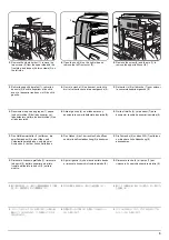
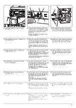
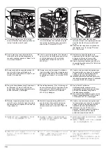
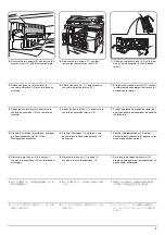
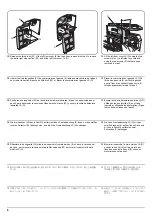
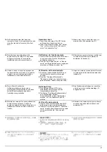
13.
Fit the hook (20) and the hole (22) of the
transfer unit (A) to the oblong hole (19) and
the projection (21) of the frame of the MFP
and secure the unit using a TP screw
M3 × 05 (L).
Arrange the cable (23) to position it under
the metal fittings (24) .
14.
Remove the screw (25) from the left rear
side of the MFP, turn the lever (26) upward,
and fit the screw (25) again to the lower hole.
13.
Placer le crochet (20) et l’orifice (22) de
l’unité de transfert (A) dans l’orifice oblong
(19) et dans la saillie (21) du cadre du MFP,
et fixer l’unité à l’aide d’une vis TP M3 × 05
(L).
Arranger le câble (23) pour le mettre en
place au-dessous des garnitures en métal
(24) .
14.
Enlever la vis (25) du côté arrière gauche du
MFP, tourner le levier (26) vers le haut, et
replacer la vis (25) dans l’orifice inférieur.
13.
Encaje el gancho (20) y el orificio (22) de la
unidad de transferencia (A) al orificio
alargado (19) y la saliente (21) del armazón
del MFP y asegure la unidad utilizando un
tornillo TP M3 × 05 (L).
Instale el cable (23) para ubicarlos debajo de
los herrajes de metal (24).
14.
Saque el tornillo (25) del lado trasero del
MFP, mueva la palanca (26) hacia arriba, y
fije el tornillo (25) de nuevo en el orificio
inferior.
13.
Den Haken (20) und das Loch (22) der
Transfereinheit (A) in das Langloch (19) und
den Vorsprung (21) des MFP-Rahmens
einpassen, und die Einheit mit einer TP-
Schraube M3 × 05 (L) sichern.
Das Kabel (23) unter den Metallbeschlägen
(24) hindurchführen.
14.
Die Schraube (25) von der linken Rückseite
des MFP entfernen, den Hebel (26) nach
oben drehen, und die Schraube (25) wieder
in das untere Loch einpassen.
13.
Inserite il gancio (20) e il foro (22) dell’unità
di trasferimento (A) nel foro oblungo (19) e
nella sporgenza (21) del telaio dell’MFP e
assicurate l’unità usando una vite TP
M3 × 05 (L).
Disponete il cavo (23) in modo da farlo
scorrere al di sotto del supporto metallico
(24).
14.
Rimuovete la vite (25) dal lato posteriore
sinistro dell’MFP, girate la leva (26) verso
l’alto e inserite di nuovo la vite (25) nel foro
inferiore.
12.
アース板 (J) をビス M3 × 05TP(L) 1 本で取
り付ける。
13.
搬送ユニット (A) のフック (20) と穴 (22)
を MFP 本体フレームの長穴 (19) と突起部
(21) に合わせて取り付け、ビス M3 ×
05TP(L)1 本で固定する。
電線 (23) が金具 (24) の下側になるように
配線する。
14.
MFP 本体左後側のビス (25)1 本を取り外し、
レバー(26) を上方向に回転させ、下側の穴に
再度ビス (25) を取り付ける。
12.
用 1 个螺丝 M3 × 05TP(L)装上地线板(J)。
13.
将输送组件(A)的挂钩(20)和孔(22)对准
MFP 主机机架的长孔(19)和突起部(21)进行
安装,并用 1 个螺丝 M3 × 05TP(L)进行固
定。
应使电线(23)配置在金属件(24)的下侧。
14.
拆下 MFP 主机左后侧的 1 个螺丝(25),将把
柄(26)向上方转动,再用螺丝(25)固定在下
侧孔。
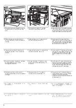
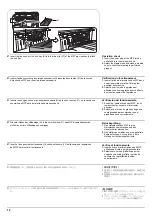
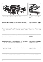
12.
Fit the ground plate (J) using a TP screw
M3 × 05 (L).
12.
Encaje la placa de tierra (J) utilizando un
tornillo TP M3 × 05 (L).
12.
Placer la plaque de masse (J) à l’aide d’une
vis TP M3 × 05 (L).
12.
Montate la piastra di terra (J) usando una
vite TP M3 × 05 (L).
12.
Die Grundplatte (J) mit einer TP-Schraube
M3 × 05 (L) befestigen.
Summary of Contents for TASKalfa 420i
Page 1: ...SERVICE MANUAL Published in May 2010 842KS113 2KSSM063 Rev 3 TASKalfa 420i TASKalfa 520i ...
Page 4: ...This page is intentionally left blank ...
Page 10: ...This page is intentionally left blank ...
Page 14: ...2KR 2KS This page is intentionally left blank ...
Page 224: ...2KR 2KS 1 4 66 This page is intentionally left blank ...
Page 328: ...2KR 2KS 2 3 30 This page is intentionally left blank ...
Page 371: ...INSTALLATION GUIDE FOR PAPER FEEDER ...
Page 381: ...INSTALLATION GUIDE FOR 3000 SHEETS PAPER FEEDER ...
Page 436: ...INSTALLATION GUIDE FOR CENTER FOLDING UNIT ...
Page 450: ...INSTALLATION GUIDE FOR MAILBOX ...
Page 458: ...INSTALLATION GUIDE FOR HOLE PUNCH UNIT ...
Page 470: ...INSTALLATION GUIDE FOR BUILT IN FINISHER ...
Page 483: ...INSTALLATION GUIDE FOR JOB SEPARATOR ...
Page 491: ...INSTALLATION GUIDE FOR FAX System ...
Page 507: ......
Page 508: ......


