background image


Kingservo 

68 

Pr

Pr

Pr

Pr41 |

41 |

41 |

41 | 


Control Pulse Reversion


A

AA

A


Initial Value

0


Setting Range

0~1 

Unit

:–


Function

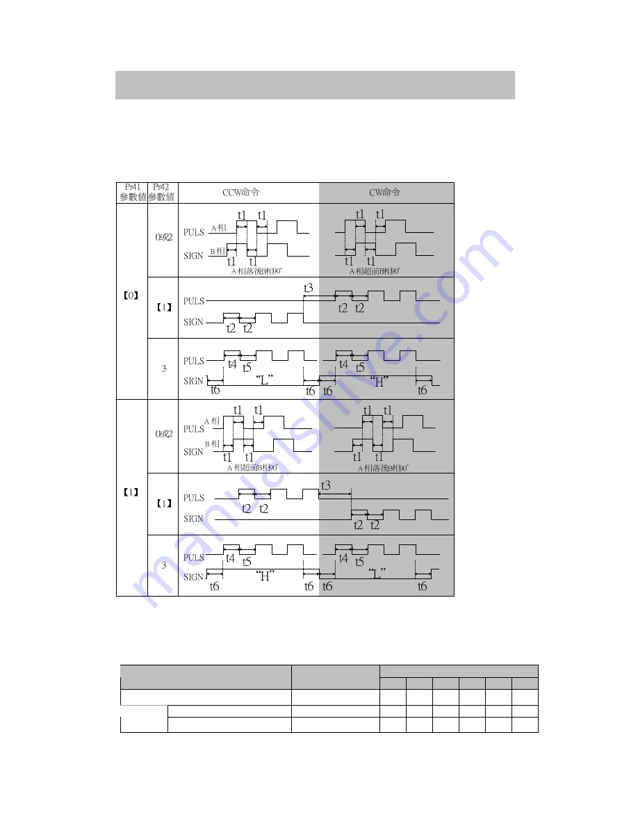
Set rotary direction and form of command pulse for command pulse input. 


Pr41=0, 
Pr42=0 or 2    Command pulse form is 9

phase differnce of 2 phase pulse(A phase+B phase)   

Pr42=1            Command pulse form is CW pulse wave line and CCW pulse wave line. 
Pr42=3            Command pulse form is pulse wave line+sign 

•Allowable maximum frequency and minimum time range of command pulse input sign. 

Minimum required time width 

PULS/SIGN Input Interface 

Allowable Input 

Maximum Frequency 

t1 

t2 

t3 

t4 

t5 

t6 

Line drive executive pusle line interface 

2Mpps 

500ns 250ns 250ns 250ns 250ns 250ns 

Lind drive interface 

500kpps 

2µs 

1µs 

1µs 

1µs 

1µs 

1µs 

Pulse line 

interface  Interface of open zone polarity 

200kpps 

5µs  2.5µs  2.5µs  2.5µs  2.5µs  2.5µs 

Rising/decending time of comman pulse input signa shall be kept lower than 0.1µs.


Summary of Contents for KSDG Series

Page 1: ...Kingservo Manual AC Servo MotorKSMA Servo Driver KSDG Series 20081014 3rd Version 135 1038 2344 QQ 9795 220 98 www kingservo com 272...

Page 2: ...ion map 13 2 2Power wiring diagram 15 2 3 Defination of Connector Pin 17 2 3 1Cable of Encoder 17 2 3 2 Power Cable of Motor 18 2 4 Communication Line of RS 232 19 2 5 Wiring of Connector I F 20 2 5 1...

Page 3: ...e of Input Loop 90 5 2 2 Wiring Reference of Output Loop 92 5 3 Function of Pins of Connector I F 94 5 3 1 Input Interface Sharing 94 5 3 2 Input Interface Pulse 98 5 3 3 Input Interface Analog Comman...

Page 4: ...KingServo 4...

Page 5: ...KingServo 5 Chapter One Identificaiotns of Products 1 1Safety Sign Warning Sign...

Page 6: ...parts are as same as the specification Check whether there is any damage to the appearance during transportation Verify whether driver motor controller and motor are the Kingservo Ac Servo series pack...

Page 7: ...ingservo AC SERVO Model No KSDG00421LI Power 400W 200 255 3PH 50 60Hz 2 8A 200 255 1PH 50 60Hz 3 5A Output 110V 3PH 0 416 6Hz 2 8A Serial No K080401010129 Kingservo Technology CO LTD Made In Taiwan In...

Page 8: ...Name plate of Servo Motor Kingservo AC SERVO MOTOR Input 3PH AC 90V 2 8A Rated Output 0 4 KW Rated Freq 250 Hz Rated Rev 3000 r min CONT TORQUE 1 3 Nm CONNECTION Y SER No K080401010165 PN BEC M080115...

Page 9: ...ingServo 9 1 5 Name of Parts 1 5 1Driver KSMG 400W 750W LED 6 SHIFT UP DOWN RS 232 SIG Kingservo I F SET MODE 2 U V W 231 203 026 000 WAGO P B1 B2 r t L1 L2 L3 231 103 026 000 WAGO 231 205 026 000 WAG...

Page 10: ...KingServo 10 1 5 2 Motor KSMA 400W 750W 4...

Page 11: ...and power line of motor U V W in accordance with connection of peripheral devices of controller and controller wiring diagram 2 Increase I F connector MDR wiring and connect them by connection of sing...

Page 12: ...KingServo 12 30 0 3 0 8 0 50h7 14 0 0 01 0 00 104 8 60 0 44 0 70 0 4 4 5 25 0 22 5 5h9 5 0 11 0...

Page 13: ...ctionor and Wiring 2 1Controller and peripheral configuration map L1 L2 L3 r t NF NF NF NF NFB NFB NFB NFB 220Vac Resistor P Resistor P Resistor P Resistor P B B B B1 1 1 1 B B B B2 2 2 2 B1 B2 B1 B2...

Page 14: ...KingServo 14 RS 232 DC24V...

Page 15: ...r t P B1 L3 L2 B2 U W V 1 1 2 3 4 4 3 2 L1 R Encode Encode NF SIG I F RS 232 NFB MC DC 24V 200V 260V 172159 1 Tyco Electronics AMP Tyco Electronics AMP 172167 1 r t P B1 L3 L2 B2 U W V 1 1 2 3 4 4 3 2...

Page 16: ...on to specification of built in flyback resistor 150 and 50W Application of Built in Flyback Resistor Keep short curicuit between B1 and B2 Set parameter Par 6C as 0 default value is 0 Application of...

Page 17: ...RX VCC GND FG Color Red Green Black White Yellow Blue Gray Orange Brown Light RED Purple Ligth Green Grounding Line of Isolation Net NO 1 2 3 4 5 6 7 8 9 10 Pin Definition GND GND VCC VCC NC A A B B C...

Page 18: ...RX RX 5V 0V A A B B Z Z RX RX FG FG 5V 0V 13 14 20 3 1 4 2 17 18 8 7 9 10 11 12 15 12 11 1 2 3 4 5 6 5V 0V Tyco Electronics AMP 172171 1 Tyco Electronics AMP 172163 1 750W 2 3 2 Power Cable of Motor P...

Page 19: ...onnecting computer and driver by RS 232 the communication software KSDTools can be set up KSDTools provides many convenient functions such as to monitor the states of motor set modify parameters and s...

Page 20: ...KingServo 20 2 5 Wiring of Connector I F 3m 30cm 3m 30cm COM COM VDC DC 12 24V 24V 50mA 1 2 GND I F FG COM COM VDC...

Page 21: ...or I F Side Connector of Driver Connector Prepared by User Name of Parts Mode Manufacturer Connector Welde d 54306 5011 or 54306 5019 leadfree Shell of Connector 54331 0501 Molex Inc Connector Welde d...

Page 22: ...26 ZERO SPD Zero speed control Input ZERO SPD Zero speed control Input 27 GAIN Gain selection GAIN Gain selection GAIN Gain selection 28 DIV DIV slection Input INSP3 The thrid choice of internal spee...

Page 23: ...4 7K 43K 43K SIGN 220 2K 2K 43K 43K SPR TRQR OPC1 OPC2 PULS1 PULS2 SIGN1 SIGN2 GND OA OA OB OB OZ OZ GND CZ GND GND CWTL SP IM 1K 1K 10K 3 83K 10K 3 83K 20K 220 220 7 33 30 29 27 28 32 31 9 8 35 34 37...

Page 24: ...KingServo 24 Speed Mode Speed Mode Speed Mode Speed Mode...

Page 25: ...M SVO ALM AT SP AT SP BK OFF BK OFF TLC ZSP COM PULSH1 PULSH2 SIGNH1 SIGNH2 4 7K SPR TRQR OPC1 OPC2 PULS1 PULS2 SIGN1 SIGN2 GND OA OA OB OB OZ OZ GND CZ GND GND CWTL SP IM 1K 1K 10K 3 83K 10K 3 83K 20...

Page 26: ...KingServo 26 72 0 67 0 5 0 132 0 Kingservo L1 L2 L3 r t P B1 B2 U V W I F SIG MODE SET RS 232...

Page 27: ...KingServo 27 Charpter Threee Panel Operation 3 1 Panel Structure MODE SET LED Error 6 LED Error LED LED MODE 5 1 2 3 EEPROM 4 5...

Page 28: ...2 Mode Category and Contents Refer to monitor mode in P29 Refer to mode of parameter setting in P35 Refer to EEPROM writing in mode in P37 Refer to rigid setting mode in P39 Refer to auxilary functio...

Page 29: ...2710 5133 SPR 10 00V LED MODE SET SET MODE MODE P30 P30 P30 P30 P30 P30 P30 P30 P30 P30 P30 P30 P31 P31 P31 P31 P31 P31 P31 P31 P32 P32 P32 P32 P33 P33 P33 P33 P33 P33 P33 P33 P33 P33 P33 P33 P33 P33...

Page 30: ...y Scope 9999 9999 value less than low limit is displayed with value over upper limit is displayed with Unit Pulse Rotary Speed of Motor sign axis core rotates along CW Non sign axis core rotates along...

Page 31: ...r not PULS INH ON POS TLC SVO ALM C MODE ALM CLR SVO RDY ZSP CLR BK OFF SVO ON CW LIMIT CCW LIMIT ZERO SPD GAIN DIV lights it means that the signal input switch is on lights it means the signal input...

Page 32: ...h error code will not be maintained in the record The causes of often occurred fautls Error Code Name Causes Err 11 Voltage protection controlling power shortage While DSP is low voltage inhibit proce...

Page 33: ...KingServo 33 Display of Software Version To display the software version of driver Alarm Display Over 85 the LED panel will keep on flickering Display of Fyback Load Rate Display of Overload Rate...

Page 34: ...g graph is display of overflow When the sum of pusls are any numbers continuously press key for about 3 seconds and the sum of regeneration pulses and command pulses will be zero clearing Display of A...

Page 35: ...to set the parameter value Use to increase valueand to decrease value After setting parmeters refer to the structure of all modes in P28 and return to choice selection Instruction After modifying par...

Page 36: ...hey are modified and completed it will display that Please first power off the driver and reopen it again While EEPROM is writing in do not shut down power or else it produce errors In case similar er...

Page 37: ...executing writing in continuously press until is displayed Modification will be effective only after it is reset While modification of setting parameters and completion of writing in sreen will displ...

Page 38: ...alue of EEPROM Operation of Execution Srceen Under option screen of press to choose execution display While executing writing in continuously press until is displayed Remarks While EEPROM is writing i...

Page 39: ...ertia rate to reduce shock to make adjustment Operation of Choosing Screen From the initial state of LED press four times to enter into rigid setting mode Now press or to set mechanical rigid factor 1...

Page 40: ...ile it doesnot connect upper level control device such as PLC Attention Separate motor and load and pluck out connector I F prior to usage For avoiding abnormaly caused by vibration user parameters es...

Page 41: ...ration of Execution Srceen Press to display execution screen 5 Servo ON Servo OFF SET SVO ON Press motor rotates along CCW press motor rotates along CW Rotate motor with the speed set according to Pr5...

Page 42: ...Clearance of Abnormality Alarm Operation of Choosing Screen From the initial state of LED press five times to enter into auxiliary mode Press to display Operation of Execution Srceen Press to display...

Page 43: ...enter into auxiliary mode Press to display Operation of Execution Srceen Press to display execution screen Instruction While in position control mode the mode is not effective While only executing au...

Page 44: ...ord Operation of Choosing Screen From the initial state of LED press five times to enter into auxiliary mode Press to display Operation of Execution Srceen Press to display execution screen 5 Instruct...

Page 45: ...funciton of every parameter Read it carefully and ajust parameters to the best operating condition before application 4 1 2 Setting Method The setting mothod of parameters is as following 1 Front pan...

Page 46: ...Speed Control and Torque Control 5B to 5E input gain setting rotary limit setting and offset adjustment of torque commander Program 60 to 6C setting of output signal detection condition of on positio...

Page 47: ...able Mode 10 First position loop gain 47 1 2000 1 S P 11 First speed loop gain 36 1 3500 Hz All 12 Time constant of first speed loop integral 28 0 1000 0 01ms All 13 First speed detection filter 0 0 5...

Page 48: ...0 0 10000 T 3D Torque control shift width 0 0 10000 T Parameter No Pr Function Pre set Value Range Unit Applicable Mode 40 Command pulse input option 0 0 1 P 41 Command pulse reversion 0 0 1 P 42 Puls...

Page 49: ...ing 0 10000 10000 rpm S T 74 Fifth speed of speed setting 0 10000 10000 rpm S 75 Sixth speed of speed setting 0 10000 10000 rpm S 76 Seventh speed of speed setting 0 10000 10000 rpm S 77 Eighth speed...

Page 50: ...osition deviation 0 0 1 P 65 On position output setting 0 0 3 P 66 State during drive inhibition input 0 0 1 All 68 Sequence control while alarm souds 0 0 3 All 69 Sequence control while server is clo...

Page 51: ...12 Unit Function Choose data type displayed by LED in the front panel during the initial stage of power being on Set Value Contents 0 Position Deviation 1 Rotary Speed of Motor 2 Torque Output 3 Contr...

Page 52: ...Mode Second Mode 0 Position 1 Speed 2 Torque 3 Position Speed 4 Position Torque 5 Speed Torque If setting is a complex mode Pr02 3 4 5 control mode shift input C MODE is used to make shift between fi...

Page 53: ...0 1 Unit Function This is the parameter that can make analog torque limit input CCWTL CWTL signal invalid 1 invalid input 0 valid input If not using torque limit function set Pr03 to 1 This parameter...

Page 54: ...LIMIT input is open meanwhile driver is judged as abnormal state Err38 drive inhibition input protection will occur 3 While used in the vertical axis and limit switch at the top of work piece acts it...

Page 55: ...ernal speed Pr53 ON OFF OFF Analog speed command CN I F Pin 14 2nd speed of internal speed Pr54 2nd speed of internal speed Pr54 2nd speed of internal speed Pr54 OFF ON OFF Analog speed command CN I F...

Page 56: ...or signal output SPM CN I F PIN 43 and motor s actual speed and intruction speed Setting Value SPM Signal Relation Between Output Voltage Level and Speed 0 6V 375rpm 1 6V 750rpm 2 6V 1500rpm 3 6V 3000...

Page 57: ...ssign function of zero speed detection ZSP CN I F PIN 12 Relation of setting value of Pr0A and ZSP output function is same with TLC output option of above Pr09 Setting Value TM Signal Relation Between...

Page 58: ...A A A A Initial Value 36 Setting Range 1 3500 Unit Hz Function Decide response of speed loop After raising position loop gain for improving response feature of servo integrity so speed loop gain also...

Page 59: ...delay filter inserted into torque commander section Effectively contain vibration caused by reversion resonance Pr1 Pr1 Pr1 Pr15 5 5 5 Positive Regeneration of Speed Initial Value 300 Setting Range 0...

Page 60: ...on Refer to Pr18 Pr Pr Pr Pr1A 1A 1A 1A Second Speed Loop Integral Time Constant A A A A Initial Value 130 Setting Range 1 1000 Unit ms Function Refer to Pr18 Pr Pr Pr Pr1B 1B 1B 1B Second Speed Detec...

Page 61: ...inertia ratio is smaller than actual ratio setting unit of speed loop gain will be smaller Pr Pr Pr Pr2 2 2 27 7 7 7 External Noise Observation A A A A Initial Value 0 Setting Range 0 8 Unit Function...

Page 62: ...ial Value 0 Setting Range 127 127 Unit 5mV Function Refer to Pr2A Pr Pr Pr Pr30 30 30 30 Second Gain Action Setting A A A A Initial Value 0 Setting Range 0 1 Unit Function Make choice to PI P action s...

Page 63: ...Level A A A A nitial Value 100 Setting Range 0 10000 Unit Function It is valid as Pr31 is set to 3 8 set determinant level of first second gain shift Pr Pr Pr Pr34 34 34 34 Position Control Shift Lev...

Page 64: ...35 35 35 35 Position Gain Shift Time A A A A Initial Value 4 Setting Range 0 10000 Unit setting value 1 ms Function As second gain shift function is valid and gain is shifting only set periodic shift...

Page 65: ...r34 Shift level width Pr Pr Pr Pr38 38 38 38 Speed Control Shift Level A A A A Initial Value 0 Setting Range 0 10000 Unit Function Refer to Pr37 Pr Pr Pr Pr39 39 39 39 Speed Control Shift Level Width...

Page 66: ...t delay time Pr33 Shift level Pr34 Shift level width Pr Pr Pr Pr3C 3C 3C 3C Torque Control Shift Level A A A A Initial Value 0 Setting Range 0 10000 Unit Function Refer to Pr3B Pr Pr Pr Pr3D 3D 3D 3D...

Page 67: ...pulse input can be input from photo coupler or line drive exclusive input Setting Value Content 0 Optical coupler I F PULS1 PIN 3 PULS2 PIN 4 SIGN1 PIN 5 SIGN2 PIN6 1 Line drive exclusive input I F PU...

Page 68: ...e Pr42 3 Command pulse form is pulse wave line sign Allowable maximum frequency and minimum time range of command pulse input sign Minimum required time width PULS SIGN Input Interface Allowable Input...

Page 69: ...put inhibition input PULS INH CN I F PIN 33 Setting Value PULS INH Input 0 Valid 1 Invalid As PULS INH is open with COM Command pulse input is inhibited If INH input is not applied set Pr43 to 1 It s...

Page 70: ...ave system is lag behind A phase wave system as they rotate along CW but B phase waves keep ahead of A phase waves as they rotate along CCW This parameter can be used to reverse logic of B phase pusle...

Page 71: ...under instruction division multiple input shift DIV CN I F PIN 28 DIV OFF Select First Numerator Pr46 DIV ON Select Second Numerator Pr47 Setting Example As division multiple ratio is equal to 1 basic...

Page 72: ...A Initial Value 0 Setting Range 0 3 Unit Function set average moving times of FIR filter multiply command pulse Pr Pr Pr Pr4A 4A 4A 4A Instruction Division Multiple Numerator Multiplication Initial V...

Page 73: ...on of instruction division multiple increases more than 10 times 2 Instruction pulse frequency is low Time constant of smooth filter has 8 types of settings Setting Value Time Constant 0 Non Filter Fu...

Page 74: ...or speed Use Pr50 to set the incline of relation between instruction input voltage and rotation numbers Standard factory setting is Pr50 500 r min V 6V input will produce 3000r min Attention 1 Don t a...

Page 75: ...rity of this parameter are not identical abnormaly action may happen to motor Pr Pr Pr Pr52 52 52 52 Speed Control OFFSET A A A A Initial Value 0 Setting Range 2047 2047 Unit 0 3mV Function This param...

Page 76: ...d of Speed Setting A A A A Initial Value 0 Setting Range 10000 10000 Unit rpm Function Refer to Pr53 Pr Pr Pr Pr55 55 55 55 Third Speed of Speed Setting A A A A Initial Value 0 Setting Range 10000 100...

Page 77: ...control As there is speed instruction of input step or internal speed setting is used action of SOFT START SOFT DOWN can ge gained Attention If connector use with position loop outside of driver do no...

Page 78: ...ed instruction to make it operate smoothly ts ts ts ts ta td ta Pr58 td Pr59 ts Pr5A 1 Use Pr58 and Pr59 respectively to set speedup and speeddown time of basic straight line section 2 If time width l...

Page 79: ...1V 100 if rated torque is gained required input voltage must be set Factory default setting value 30 represents 3V 100 Pr Pr Pr Pr5D 5D 5D 5D Torquq Control Input Reversion A A A A Initial Value 0 Set...

Page 80: ...otor maximum torque generation limit In the usual situation instantaneous allowable torque is the 3 times of rated torque But as 3 times of torque may damage motor load mechanic strength use this para...

Page 81: ...reach setting value range output on position signal ON POS The basic unit of deviation pulse is the resolution of used encoder as to different encoders the following contents are different 17digitals...

Page 82: ...detection signal ZSP CW Pr61 Pr61 ON CCW ZSP Pr62 Speed Attainment Initial Value 1000 Setting Range 10 10000 Unit rpm Function In speed control mode and torque control mode directly use r min to set...

Page 83: ...tion Excess Protection 0 Valid 1 Invalid As detaining pulses is over the determinant level set by Pr63 it will not be treated as abnormality and continue action Pr Pr Pr Pr6 6 6 65 5 5 5 On n n n Posi...

Page 84: ...nter 0 DB Free run Hold 1 Free run Free run Hold Pr Pr Pr Pr68 68 68 68 Sequence Control While Alarm Sounds A A A A Initial Value 0 Setting Range 0 3 Unit Function Set drive condition of speeddown and...

Page 85: ...ear 4 DB DB Hold 5 Free run DB Hold 6 DB Free run Hold 7 Free run Free run Hold DB dynamic brake action Pr Pr Pr Pr6A 6A 6A 6A Set Mechanic Brake Action Time as Server is OFF Initial Value 0 Setting R...

Page 86: ...Resistance Impressing Option Initial Value 0 Setting Range 0 2 Unit Function Directly use internal retrogradation resistance or chop away internal retrogradation resistance and install retrogradation...

Page 87: ...Speed of Speed Setting A A A A Initial Value 0 Setting Range 10000 10000 Unit rpm Function Refer to Pr53 Pr76 Pr76 Pr76 Pr76 Seventh Speed of Speed Setting A A A A Initial Value 0 Setting Range 10000...

Page 88: ...Kingservo 88...

Page 89: ...ignal GND Ground of analog signal 26 ZERO SPD Zero speed control Input ZERO SPD Zero speed control Input 27 GAIN Gain selection GAIN Gain selection GAIN Gain selection 28 DIV DIV slection Input INSP3...

Page 90: ...transmission way that is not easily affected by noise and improves the precision of signal transmisson 2 Open set I F Input pulse frequency 200Kpps This method need use external control signal power V...

Page 91: ...of signal transmisson as line driver I F is used represents twisted pair Analog command input Analog command has 3 goups SPR TRQR Pin 14 CCWTL Pin16 and CWTL Pin18 Alowable maximum input voltage is 10...

Page 92: ...to receive controller side upper level controller The 300 terminal resistor shall be added beween input and reception of line driver Non insulated outpput Analog monitor output It be divide into two t...

Page 93: ...tputed through open set poarity of transistor and used to connect relay and photo coupler As output of transistor is ON voltage of Vce is about 1V Generally TTLIC can not be connected directly Transis...

Page 94: ...brake action as CW LIMIT is valid Factrory setting value is emergent cease of dynamic brake Pr66 is 0 CCW inhibition limit input 9 CCW LIMIT CCW drive inhibition input CCW LIMIT As the active part of...

Page 95: ...rent control modes Position control Division multiple numerator of shiftable command pulse As short curcuit with COM instruction division multiple numerator shift from Pr46 1st instruction division mu...

Page 96: ...ounter Can select clearance mode in Pr4D counter clerance input mode Pr4D 0 As CLR shorts with COM clear deviation counter 1 Fatory value As connection of CLR and COM is shifted from open to short onl...

Page 97: ...erent control modes Position control Command pusle input inhibition input PULS INH If open with COM donot receive position pulse command This input can make Pr43 command pulse inhibiton input invalidi...

Page 98: ...s 2Mpps Use Pr41 control pulse reversion and Pr42 pulse input mode setting to select 6 types of command pulse input form about more details refer to the following input forms of command pulse Pulse Tr...

Page 99: ...s 1 s 1 s 1 s Pulse Train photo coupler Interface Open collector Interface 200kpps 5 s 2 5 s 2 5 s 2 5 s 2 5 s 2 5 s rising declining time of command pulse input signal shall be controlled under 0 1...

Page 100: ...fferent functions as Pr5B torque command option Pr5 B Content 0 Torque command TROR Settings of gain polarity and OFFSET of torque are as following Pr5C torque command input gain Pr51 torque command i...

Page 101: ...WTL Apply positive voltage 0 10V to limit CCW torque about 3V rated torque As Pr03 torque limit option Setting is not 0 input is invalid A D convertor resolution of the input is 12Bit including sign s...

Page 102: ...real speed of motor is over Pr62 speed attainment transistor output is ON Zero speed detection output 12 41 ZSP COM Output signals have different meaning as Pr0A ZSP output option Standard factory set...

Page 103: ...ue monitor TM option output signals have different meanings Use values of Pr08 to set proportion Pr08 Signal Meaning Function 0 2 Torque command Polar voltage output with equal proportion of motor tor...

Page 104: ...KingServo 104...

Page 105: ...KingServo 105 Chapter Six Documenets 6 1Dimension Drawing Controller KSDG 400W 72 0 67 0 167 0 157 0 5 0 132 0 Kingservo L1 L2 L3 r t P B1 B2 U V W I F SIG 220V Resistor Motor MODE SET RS 232...

Page 106: ...KingServo 106 Motor KSMA 400W 50h7 44 0 5 0 11 0...

Page 107: ...ignal process sequence as power quence as power quence as power quence as power up up up up 100ms 1s 5ms 2ms 40ms 5ms Ready Servo On Brake Off OFF ON OFF ON OFF ON Attention Above charter represents t...

Page 108: ...T represents setting value of Pr6B or the quicker time as motor speed is under 30rpm As motor ceases T has no relation with Pr6A and is 0 About operation of dynamic brake refer to instruction of Pr68...

Page 109: ...ck Attention T represents setting value of Pr6A About operation of dynamic brake in Servo Off refer to instruction parameter setting of all control modes of Pr69 sequence diagram of Servo Off Motor sp...

Page 110: ...time as motor speed is under 30rpm Even in the process of motor speeddown if restarting SRV ON signal it will not shift to Servo ON state before motor ceases Motor speed must be under 30rpm or else S...

Page 111: ...ime can not be shortened As comamand pulse input can not be equal to rise Pr16 positve regeneration filter can properly improve the performance Adjustment of Speed Mode Except positon loop gain and po...

Page 112: ...KingServo 112 6 4 S T Feature of Motor 1000 2000 3000 4000 5000 0 2 0 4 0 0 10 20 30 40 50 100 85 6 5 Feature of Overload Time Limit...

Page 113: ...o electronics Connector Pin 170365 1 11 Tyco electronics Air connector of encoder connection cable 6 6 2 Specification of SCSI II Connector Related connector prepard by user Connector of diver side Pa...

Page 114: ...nitor 1 Speed monitor Monitor pratical speed of motor or command speed Use parameter to set monitor content and scale proportion 2 Torque monitor monitor torque command about 3V rated torque deviation...

Page 115: ...y filter of command input select 1 position control useed in rigidest machine 2 start FIR filter agaistposition control useed in rigidest machine P O S I T I O N Analog input Torque limit command inpu...

Page 116: ...no wiring line function shield Following signals don t use sheild enclosure 1 over trip drive inhibition 2 torque limit 3 command pulse inhibition 4 zero speed clamp Encoder Feedback Pulse Division Se...

Page 117: ...KingServo 117 KINGSERVO TECHNOLOGY CO LTD...

Reviews: