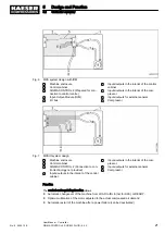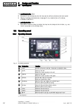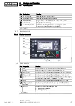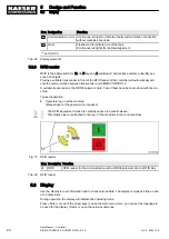
6 . 1 b a r
0 8 : 1 5 A M
8 0 ° C
Header
------------------------------
Load
Current operating mode
------------------------------
Key
– on ¦
pA
– on
Operating parameters
------------------------------
Run
2500h
Load
2490h
Operating parameters
Maintenance in
500h
Maintenance indicator
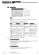
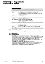
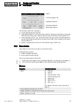
The following parameters are displayed:
■ Current operational state of machine
■ On the left-hand side of "¦" you can see from where the compressor is switched on (in the illus‐
trated example via the green «ON» key) and what the current status is (in the example "on").
■ On the right-hand side of "¦", you can see the mode of the load control (in the illustrated exam‐
ple, the network nominal pressure pA is active) and the mode of the compressor (in the exam‐
ple it is switched on).
■ Number of operating hours and hours of the machine being in LOAD mode.
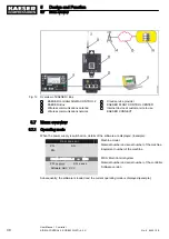
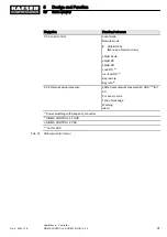
5.7.2 Menu structure
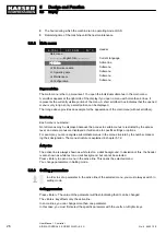
Press «Enter» or one of the arrow keys to open the main menu.
In the main menu, you can:
■ Retrieve displayed information
■ Enter customer-specific settings
The menus shown require access level 2.
Depending on the software version of SIGMA CONTROL 2, machine type and available op‐
tions, only the menus that are available for this particular machine will be displayed.
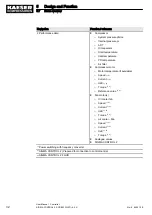
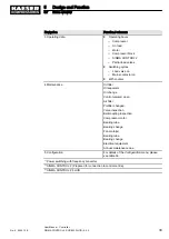
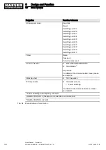
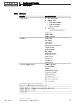
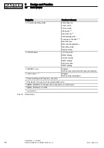
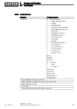
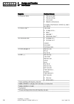
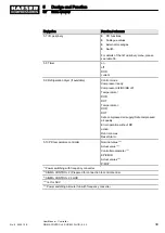
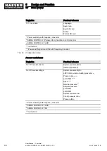
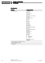
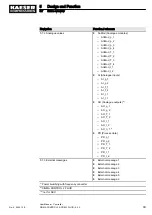
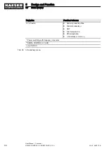
Main menu
Navigation
Function / submenu
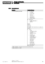
1 Status
■ Messages
■ Statistics
■ Current pressure control
■ Current operating mode
■ DI/DO status
■ pN/ADT curve
■ pN/n curve
1)
4)
For details of the
Status menu, please see ta‐
1)
Power switching with frequency converter
3)
SIGMA CONTROL 2 (Prepared for connection to control centre)
4)
SIGMA CONTROL 2 FLUID
5
Design and Function
5.7
Menu overview
No.: 9_9450 12 E
User Manual Controller
SIGMA CONTROL 2 SCREW FLUID ≥5.0.X
31

