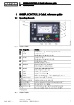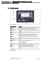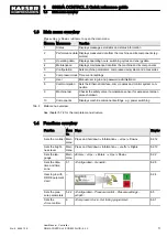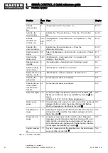
Fig. 1 Operating elements ....................................................................................................................
1
Fig. 2 Indicator elements ......................................................................................................................
2
Fig. 3 MCS interfaces ...........................................................................................................................
11
Fig. 4 MCSIO interfaces .......................................................................................................................
12
Fig. 5 KAESER i.Box − indicator elements and interfaces ...................................................................
17
Fig. 6 MCS system design with IOM ....................................................................................................
21
Fig. 7 MCSIO system design ................................................................................................................
21
Fig. 8 Operating elements ....................................................................................................................
22
Fig. 9 Display elements ........................................................................................................................
23
Fig. 10 RFID reader ................................................................................................................................
24
Fig. 11 KAESER CONNECT for SIGMA CONTROL 2 ...........................................................................
28
Fig. 12 Overview of KAESER i.Box ........................................................................................................
30
Fig. 13 Back of the RFID Equipment Card .............................................................................................
60
Fig. 14 User log-in with RFID Equipment Card ......................................................................................
60
Fig. 15 User log-in with RFID Equipment Card ......................................................................................
61
Fig. 16 Manual user log-on .....................................................................................................................
63
Fig. 17 Log-in mask ................................................................................................................................
77
Fig. 18 KAESER CONNECT for SIGMA CONTROL 2 ...........................................................................
77
Fig. 19 Select language: window ............................................................................................................
78
Fig. 20
System status menu ...................................................................................................................
78
Fig. 21 Main menu ..................................................................................................................................
79
Fig. 22
Graphs (illustration similar) .........................................................................................................
80
Fig. 23 Control keys ...............................................................................................................................
80
Fig. 24
Messages (illustration similar) ....................................................................................................
82
Fig. 25
I/O display (illustration similar) ...................................................................................................
83
Fig. 26
User management menu ............................................................................................................
84
Fig. 27
Log on for write access: window ................................................................................................
84
Fig. 28
User management menu ............................................................................................................
85
Fig. 29
Settings menu ............................................................................................................................
86
Fig. 30
Backup menu .............................................................................................................................
87
Fig. 31
Data recording menu ..................................................................................................................
88
Fig. 32 Wiring of the PROFIBUS connection ......................................................................................... 126
Fig. 33 Electrical diagram example with SIGMA AIR MANAGER .......................................................... 127
Fig. 34 Communication interface ............................................................................................................ 128
Fig. 35 Insert the communication module. ............................................................................................. 129
Fig. 36 Front plate communication module PROFIBUS ......................................................................... 130
Fig. 37 Direct connection of two SIGMA CONTROL 2 ........................................................................... 135
Fig. 38 LOAD remote contact ................................................................................................................. 141
Fig. 39 Wiring diagram for local/LOAD remote contact: ......................................................................... 143
Fig. 40 Machine with pressure switch regulation .................................................................................... 148
Fig. 41 Function diagram ........................................................................................................................ 151
Fig. 42 Switching the compressed air station on and off ........................................................................ 176
Fig. 43 Switching off in an emergency ................................................................................................... 177
Fig. 44 Acknowledging messages .......................................................................................................... 178
List of Illustrations
No.: 9_9450 12 E
User Manual Controller
SIGMA CONTROL 2 SCREW FLUID ≥5.0.X
v


