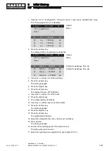
4. Break the other fins in the same manner.
5. Remove the plastic cover
7
.
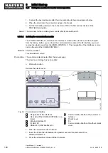
Inserting and fixing the communication module
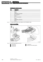
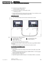
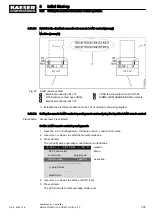
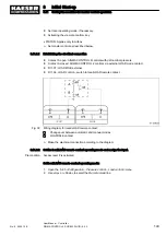
Align the communications module as shown in Figure 35.
Precondition The plastic cover is removed.
Fig. 35 Insert the communication module.
1
Bay, interface X4
2
Communications module
3
Front plate
4
Fastening screws
5
Cable connector, communication module
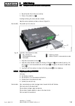
1. Align the communication module
2
.
2. Insert the communication module into the bay of interface X4
1
until it latches (see Fig. 35).
The module is correctly installed when its front plate
3
sits tightly in the recess of shaft inter‐
face X4
1
.
3. Use the Torx T9 screwdriver to screw in the fixing screws
4
to hand tightness.
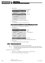
8.11.3.2 Activating operation via PROFIBUS
Overview:
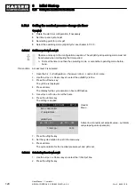
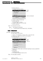
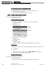
■ Set the slave number
■ Set reaction for a communication malfunction.
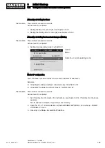
■ Activate the communications module
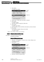
■ Activate the remote mode
Precondition The communication module is plugged and screwed into the X4 interface.
The bus is wired to the bus master.
The machine's voltage supply is activated.
The machine is parametrised as a slave in the bus master.
The bus master is operational.
8
Initial Start-up
8.11 Setting the machine for master control operation
No.: 9_9450 12 E
User Manual Controller
SIGMA CONTROL 2 SCREW FLUID ≥5.0.X
129

