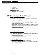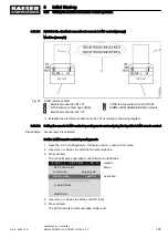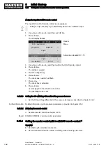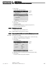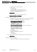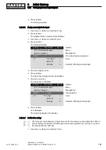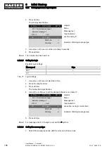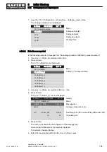
2. Press «Enter».
The
DI display flashes.
6 . 1 b a r
0 8 : 1 5 A M
8 0 ° C
Header
5.2.3 Load control
Menu
pA/pB RC
DI1.05
☑
Active line
Logic :
+
pA/pB DO
DOR1.04
☐
Logic :
+
·········
Load RC
DI1.07
ok ☑
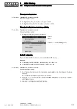
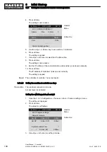
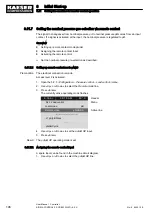
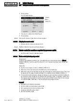
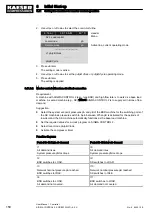
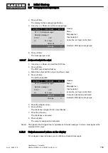
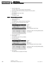
3. Use «Up »or «Down» to set the
DI input.
4. Press «Enter».
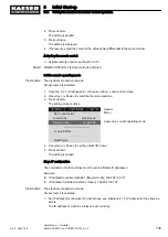
Result The input for remote contact has now been assigned.
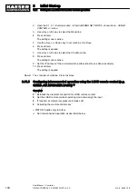
8.11.7.3 Activating the remote control
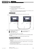
➤ Activate remote control see chapter 8.2.13.
Result SIGMA CONTROL 2 remote control is activated.
8.11.8 Master control for machines regulated by pressure switch
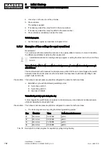
➤ Set the master control as described below.
8.11.8.1 Master control via floating relay contact
Requirement:
A machine with SIGMA CONTROL 2 (e.g. series BSD) and a conventional machine without
SIGMA CONTROL 2 with the same flow rate are to run in sequence as base load or peak load
machines.
Suggestion:
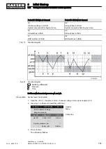
■ Set the clock program or clock on SIGMA CONTROL 2.
■ Select local mode with time control pA/pB Clock or clock pA/pB Cycle.
■ Select the network nominal pressures pA and pB analogous to the required values. They must
be identical to the pressure switch settings on the machine without SIGMA CONTROL 2.
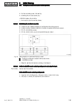
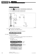
■ To make the nominal pressure changeover between the two machines possible, a floating re‐
lay contact must be assigned to the selected local operating mode. An auxiliary contactor can
be energised via this contact to activate the pressure switches for pA and pB on the compres‐
sor without SIGMA CONTROL 2. See the example wiring diagram below.
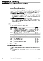
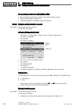
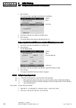
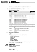
Overview
■ Establishing the electrical connection
■ Set the network nominal pressure pA and pB.
■ Set operating mode in local operating mode
■ Assigning the floating relay contact
■ Set local operating mode
8
Initial Start-up
8.11 Setting the machine for master control operation
No.: 9_9450 12 E
User Manual Controller
SIGMA CONTROL 2 SCREW FLUID ≥5.0.X
147

