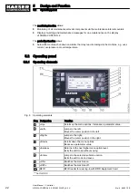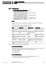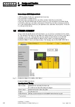
5.3.1 Operating mode
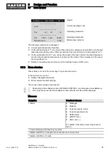
6 . 1 b a r
0 8 : 1 5 A M
8 0 ° C
Header
------------------------------
Load
Current operating mode
------------------------------
Key
– on ¦
pA
– on
Operating parameters
------------------------------
Run
2500h
Load
2490h
Operating parameters
Maintenance in
500h
Maintenance indicator
Header
The header is the topmost line on the display. It is always shown as white text on a black back‐
ground.
Important information and values are displayed in the header.
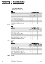
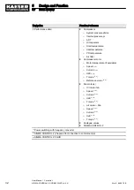
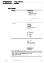
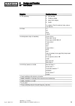
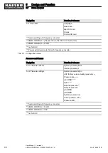
The displayed data varies depending on the machine type:
Type
Header, left
Header, centre
Header, right
SIGMA CONTROL 2
FLUID
Working gauge pressure Time
Airend discharge temper‐
ature
SIGMA CONTROL 2
DRY
Pressure display reading
point
Pressure at the com‐
pressed air outlet
p100
Current operating mode
SIGMA CONTROL 2
VAC
Working gauge pressure Time
Airend discharge temper‐
ature
SIGMA CONTROL 2
BLOWER
p2 (final pressure)
Time
Discharge temperature T2
SIGMA CONTROL 2
BOOSTER
Pressure at the com‐
pressed air inlet p1
Temperature at the
compressed air out‐
let T2
Pressure at the com‐
pressed air outlet p4
SIGMA CONTROL 2
PISTON
Working gauge pressure –
Time
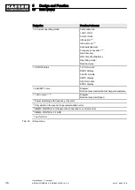
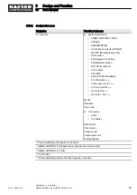
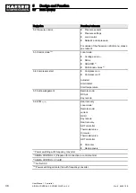
Tab. 30 Data in the header depending on the machine type
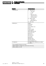
Lines 3 and 5: Operational state
Depending on the settings, either the current state of the machine or a menu text is shown in line 3.
The following parameters with their current values are displayed in line 5:
■ Remote control yes/no
■ Time control yes/no
■ Pressure control
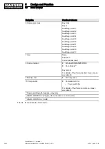
Lines 7 and 8: Machine state
The following parameters with their current values are displayed in lines 7 and 8:
■ The hours during which the machine was activated
5
Design and Function
5.3
Display
No.: 9_9450 12 E
User Manual Controller
SIGMA CONTROL 2 SCREW FLUID ≥5.0.X
25

