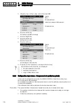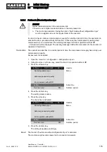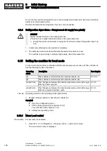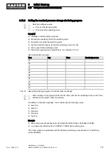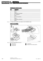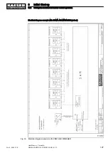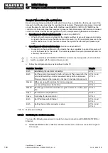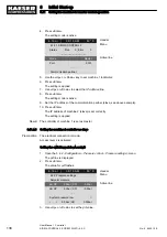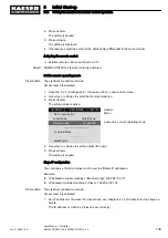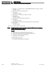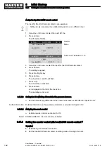
1. Connect the bus devices one after the other according to the pin assignment below.
2. Place the shield onto the connector casings at both ends.
3. Set the terminating resistor in the connector to ON for the first and last devices of the
PROFIBUS connection.
Result The terminals for the remaining bus conduit (2A/2B) are switched off.
8.11.3.1 Installing the communication module
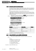
The SIGMA CONTROL 2 communication interface is closed with a plastic cover when shipped
from the factory. Before you can insert the communication module in the X4 interface, you must
remove the plastic cover from the SIGMA CONTROL 2 . The designation of the interfaces is provi‐
ded on the rear of the SIGMA CONTROL 2.
Material Small screwdriver
Torx screwdriver, size 9
Precondition The machine is disconnected from the power supply.
The absence of voltage has been verified
➤ Work with caution.
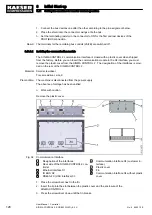
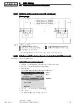
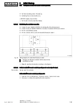
Remove the plastic cover.
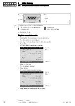
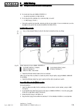
Fig. 34 Communication interface
1
Designation of the interfaces
2
Rear side of the SIGMA CONTROL 2 con‐
troller
3
Ethernet interface X1
4
IO BUS X2
5
RS485–FC (USS interface) X3
6
Communication interface X4 (customer in‐
terface)
7
Plastic cover
8
Fin
9
Communication interface X4 without plastic
cover
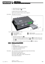
1. Place the screwdriver next to the fin.
2. Insert the tip into the slot between the plastic cover and the enclosure of the
SIGMA CONTROL 2.
3. Press the screwdriver down until the fin breaks.
8
Initial Start-up
8.11 Setting the machine for master control operation
128
User Manual Controller
SIGMA CONTROL 2 SCREW FLUID ≥5.0.X
No.: 9_9450 12 E

