21
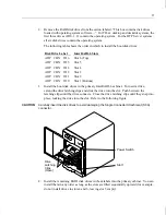
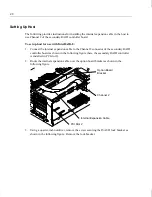
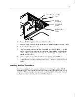
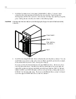
4. Remove the blanking plate from an available ISA I/O slot.
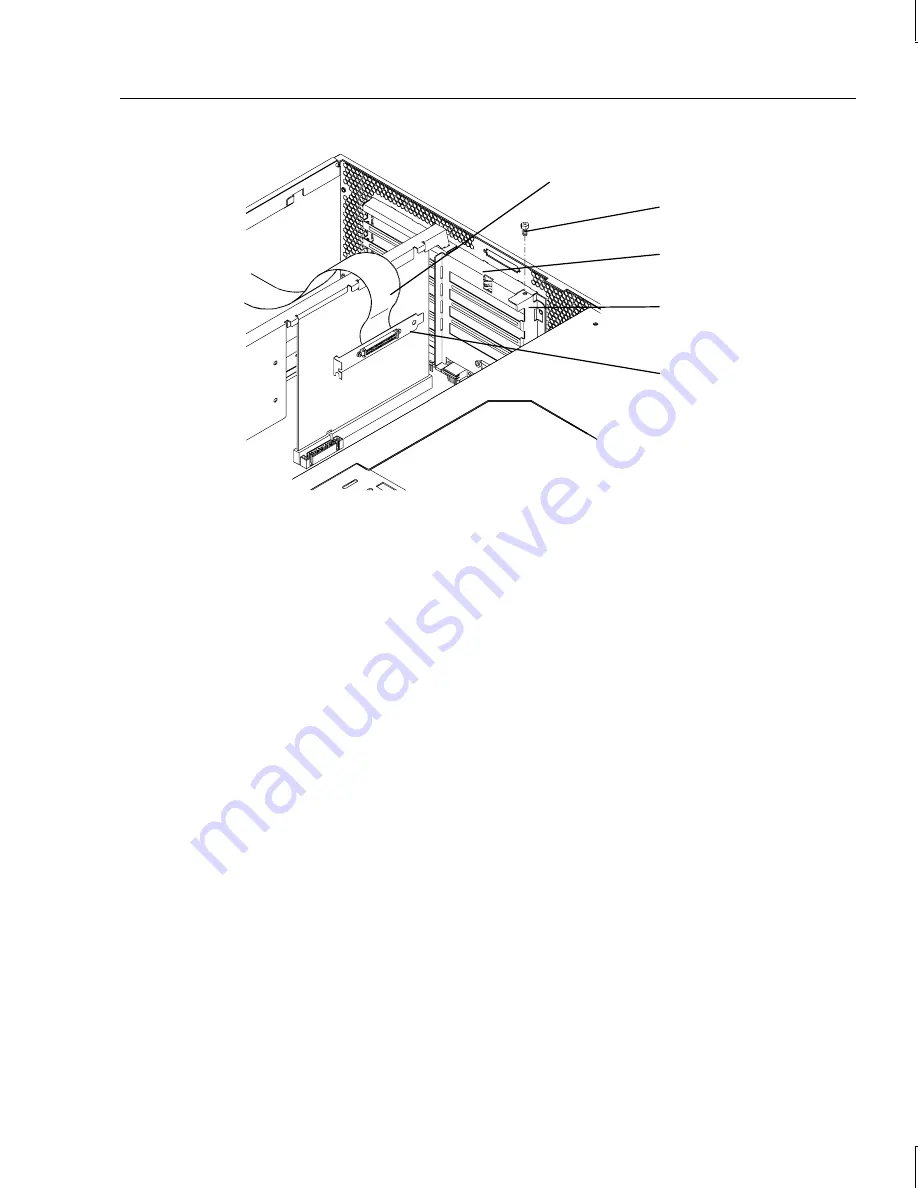
5. Install the RAID connector bracket of the internal expansion cable into the ISA I/O slot.
6. Replace the ISA I/O lock bracket.
7. For each additional internal expansion you want to add, refer to Chapter 1, “Getting
Started,” for PCI slot designations for your system. Install another RAID controller
board into the appropriate PCI slot, and repeat steps 1 through 6 to install another
internal expansion cable.
8. Close the system’s base unit as described in your system’s documentation.
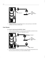
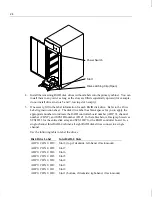
9. Connect the disk array to the system as described in “Connecting InterRAID-8 to the
System.”
Installing Multiple Expansions
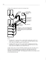
Once you understand how to expand a configuration by installing an additional RAID
controller board and an internal expansion cable, refer to the following figure to continue
expanding. The figure depicts two expansions supporting a total of nine single-channel,
deskside, disk arrays (including the internal RAID subsystem).
Internal Expansion Cable
ISA I/O
Slot Panel
Screw
ISA I/O Lock
Bracket
RAID Connector
Bracket
Summary of Contents for InterRAID-12
Page 1: ...InterRAID Hardware User s Guide January 1997 DHA018210 ...
Page 4: ......
Page 121: ...106 ...
Page 157: ...142 ...
Page 163: ...148 ...
Page 171: ...156 ...

