


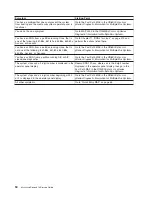


Symptom
Action
Service
Actions
You
have
an
open
service
event
in
the
service
action
event
log.
Go
to
“Service
Focal
Point”
on
page
43.
You
have
parts
to
exchange
or
a
corrective
action
to
perform.
1.
Go
to
Chapter
9,
“Removal
and
Replacement
Procedures,”
on
page
279.
2.
Go
to
″
MAP
0410:
Repair
Checkout
″
in
the
RS/6000
Eserver
pSeries
Diagnostic
Information
for
Multiple
Bus
Systems
.
You
need
to
verify
that
a
part
exchange
or
corrective
action
corrected
the
problem.
Go
to
″
MAP
0410:
Repair
Checkout
″
in
the
RS/6000
Eserver
pSeries
Diagnostic
Information
for
Multiple
Bus
Systems
.
You
need
to
verify
correct
system
operation.
Go
to
″
MAP
0410:
Repair
Checkout
″
in
the
RS/6000
Eserver
pSeries
Diagnostic
Information
for
Multiple
Bus
Systems
.
The
rack
indicator
LED
does
not
operate
as
expected.
The
rack
indicator
LED
does
not
turn
on,
but
a
drawer
identify
LED
is
on.
1.
Make
sure
the
rack
indicator
LED
is
properly
mounted
to
the
rack.
2.
Make
sure
that
the
rack
identify
LED
is
properly
cabled
to
the
bus
bar
on
the
rack
and
to
the
drawer
identify
LED
connector.
3.
Replace
the
following
parts
one
at
a
time:
v
rack
LED
to
bus
bar
cable
v
LED
bus
bar
to
drawer
cable
v
LED
bus
bar
4.
Call
support
The
system
attention
LED
on
the
operator
panel
is
on.
The
system
attention
LED
on
the
operator
panel
is
on.
Go
to
“System
Attention
LED”
on
page
40
and
perform
the
listed
actions.
OK
does
not
appear
in
the
operator
panel
display
before
pressing
the
power-on
button.
Other
symptoms
appear
in
the
operator
panel
display
or
LEDs
before
the
power
on
button
is
pressed.
A
bouncing
or
scrolling
ball
remains
on
the
operator
panel
display,
or
the
operator
panel
display
is
filled
with
dashes
or
blocks.
Verify
the
operator
panel
cable
from
the
operator
panel
to
the
CEC
backplane
is
connected
and
properly
seated
at
both
ends.
If
an
ASCII
terminal
is
available,
connect
it
to
the
system
through
serial
port
1.
v
If
the
service
processor
menu
is
displayed,
replace
the
operator
panel
assembly,
location
U0.1-L1.
Refer
to
“Operator
Panel
and
Power
Cable”
on
page
342.
v
If
the
service
processor
menu
is
not
displayed,
replace
the
service
processor,
location:
U0.1-P1-X1
(See
notes
on
page
53).
If
an
ASCII
terminal
is
not
available,
replace
the
following
one
at
a
time.
1.
Operator
panel
assembly,
location:
U0.1-L1.
Refer
to
“Operator
Panel
and
Power
Cable”
on
page
342.
2.
Service
processor,
location:
U0.1-P1-X1.
(See
notes
on
page
53).
56
Eserver
pSeries
615
Service
Guide
Summary of Contents for P 615 series
Page 1: ...pSeries 615 Service Guide SA38 0630 02 ERserver...
Page 2: ......
Page 3: ...pSeries 615 Service Guide SA38 0630 02 ERserver...
Page 12: ...x EserverpSeries 615 Service Guide...
Page 16: ...xiv EserverpSeries 615 Service Guide...
Page 18: ...xvi EserverpSeries 615 Service Guide...
Page 58: ...38 EserverpSeries 615 Service Guide...
Page 72: ...52 EserverpSeries 615 Service Guide...
Page 150: ...130 EserverpSeries 615 Service Guide...
Page 178: ...158 EserverpSeries 615 Service Guide...
Page 284: ...264 EserverpSeries 615 Service Guide...
Page 384: ...364 EserverpSeries 615 Service Guide...
Page 388: ...Model 6C3Parts 5 5 7 6 6 2 3 1 4 368 EserverpSeries 615 Service Guide...
Page 394: ...374 EserverpSeries 615 Service Guide...
Page 418: ...398 EserverpSeries 615 Service Guide...
Page 422: ...402 EserverpSeries 615 Service Guide...
Page 438: ...418 EserverpSeries 615 Service Guide...
Page 448: ...428 EserverpSeries 615 Service Guide...
Page 452: ...432 EserverpSeries 615 Service Guide...
Page 489: ......
Page 490: ...Printed in U S A October 2003 SA38 0630 02...
Page 491: ...Spine information pSeries 615 EserverpSeries 615 Service Guide SA38 0630 02...


