


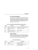


Smart Ethernet Only
21
Smart Ethernet Only
SMART
The SMART sidehead with gray sidebar indicates a feature
applicable to “smart” Ethernet Interface only. Refer to page 17 for a
description of the Smart Ethernet.
Logical Printer Architecture
SMART
The Ethernet Interface implements a logical printer architecture
which gives the system administrator the possibility to configure the
print server to handle and act upon the print data in several ways.
When a print job comes through the print server, there is a certain
logical print path that it follows before it gets to the printer. Each
logical print path consists of a sequence of logical steps where
extra processing may be performed on the print data before it is
sent to the printer. This ability to preprocess the print data before it
is sent to the printer allows elimination of certain printing problems,
or implementation of printer enhancements that may be difficult and
time consuming to solve or introduce at the system, spool file or
queue level. The preprocess ability is also simplistic to perform at
the print server level.
NOTE: If the printer is configured for IPDS, any reference to
“d4prn” should be understood to mean “dipdsprn.” This
queue should only be used to print IPDS.
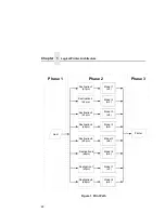
The logical print path for a print job going through the Ethernet
Interface consists of three different phases:
•
Phase 1 - the host sends the job to a destination or queue on
the Ethernet Interface (e.g. d1prn).
•
Phase 2 - the print job passes through the associated “model”
(e.g. model “m1”) on the Ethernet Interface for any extra
processing associated with the model.
•
Phase 3 - the processed print job is directed to the printer for
output.
Logical Printer Architecture
Summary of Contents for 4400 Series
Page 2: ......
Page 3: ...G544 5769 03 User s Manual 4400 Series Thermal Printer Basic And Smart Ethernet Interface ...
Page 14: ...Table of Contents ...
Page 30: ...Chapter 1 Interfaces 30 ...
Page 48: ...Chapter 3 Network Configuration 48 Novell Network Figure 8 Novell Network Configuration ...
Page 72: ...Chapter 3 IBM Printing Systems 72 ...
Page 90: ...Chapter 4 Windows Host Configuration 90 8 Select Custom and click Settings ...
Page 92: ...Chapter 4 Windows Host Configuration 92 10 Click Next 11 Click Finish ...
Page 94: ...Chapter 4 Windows Host Configuration 94 14 Select Yes then click Next 15 Click Next ...
Page 108: ...Chapter 4 Windows Troubleshooting Tips 108 ...
Page 128: ...Chapter 5 Unix Troubleshooting Tips 128 ...
Page 184: ...Chapter 8 OS 2 Workstation Configuration 184 ...
Page 200: ...Chapter 9 AS 400 ASCII Troubleshooting 200 ...
Page 242: ...Chapter 11 Handling MVS Connectivity Problems 242 ...
Page 256: ...Chapter 13 Monitoring Tools 256 ...
Page 284: ...Chapter 15 Complete Command List 284 ...
Page 292: ...Chapter 16 Ethernet Interface Naming Schemes 292 ...
Page 304: ...Communication Statements 304 ...
Page 310: ...Chapter 310 ...
Page 322: ...Index 322 ...
Page 325: ......