10/100Base-T
25
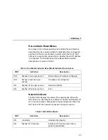
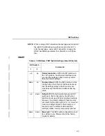
Run and Auto Reset Modes
Run mode is the normal operating state of the Ethernet Interface.
Auto Reset mode is entered when the watchdog timer is triggered
and the Print Server resets itself. In either mode, the STAT LED
flashes at a varying rate, depending on whether the unit IP address
is configured. The Run Mode and Auto Reset Mode indicator
descriptions are given in Table 1.
Network Indicator
The NET LED displays the status of the network link. When the
NET LED is on, link integrity is confirmed. The NET LED flashes off
for 1/3 second when a data packet is being transferred. When the
NET LED is off, the network connection has been severed.
Table 1. Run Mode and Auto Reset Mode Indicator Descriptions
STAT
Indication
Description
OFF
flashes on once per second
Normal Mode, IP address configured
OFF
flashes on two times per
second
IP address not configured
ON
flashes off once per second
Download (MOS)
ON
flashes off twice per second
Error
Table 2. NET LED Indicator
NET
Indication
Description
ON
constantly
Indicates link integrity
ON
flashes off 1/3 second
Flashes off 1/3 second each time a
packet is transmitted
Summary of Contents for 4400 Series
Page 2: ......
Page 3: ...G544 5769 03 User s Manual 4400 Series Thermal Printer Basic And Smart Ethernet Interface ...
Page 14: ...Table of Contents ...
Page 30: ...Chapter 1 Interfaces 30 ...
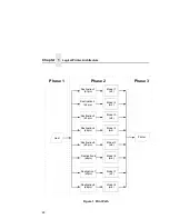
Page 48: ...Chapter 3 Network Configuration 48 Novell Network Figure 8 Novell Network Configuration ...
Page 72: ...Chapter 3 IBM Printing Systems 72 ...
Page 90: ...Chapter 4 Windows Host Configuration 90 8 Select Custom and click Settings ...
Page 92: ...Chapter 4 Windows Host Configuration 92 10 Click Next 11 Click Finish ...
Page 94: ...Chapter 4 Windows Host Configuration 94 14 Select Yes then click Next 15 Click Next ...
Page 108: ...Chapter 4 Windows Troubleshooting Tips 108 ...
Page 128: ...Chapter 5 Unix Troubleshooting Tips 128 ...
Page 184: ...Chapter 8 OS 2 Workstation Configuration 184 ...
Page 200: ...Chapter 9 AS 400 ASCII Troubleshooting 200 ...
Page 242: ...Chapter 11 Handling MVS Connectivity Problems 242 ...
Page 256: ...Chapter 13 Monitoring Tools 256 ...
Page 284: ...Chapter 15 Complete Command List 284 ...
Page 292: ...Chapter 16 Ethernet Interface Naming Schemes 292 ...
Page 304: ...Communication Statements 304 ...
Page 310: ...Chapter 310 ...
Page 322: ...Index 322 ...
Page 325: ......


