v
DIMMs
must
be
installed
in
groups
of
eight
(octals).
v
DIMMs
are
installed
in
the
following
order:
–
A-B-C-D-E-F-G-H
–
J-K-L-M-N-P-Q-R
–
S-T-U-V-W-X-Y-Z
–
1-2-3-4-5-6-7-8
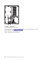
Figure
4.
Network
Interface
Controller
(NIC)
port
locations
Note:
The
physical
port
connectors
may
vary
by
CCIN.
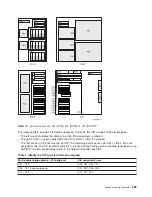
Figure
5.
Network
Interface
Controller
(NIC)
HSL
port
and
LED
locations
268
Hardware
(Remove
and
Replace;
Part
Locations
and
Listings)
Summary of Contents for 270
Page 2: ......
Page 12: ...x Hardware Remove and Replace Part Locations and Listings...
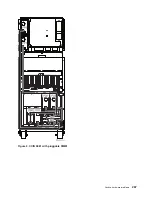
Page 279: ...Figure 3 CCIN 2881 with pluggable DIMM Analyze hardware problems 267...
Page 281: ...Figure 6 Models 830 SB2 with FC 9074 HSL and SPCN locations Analyze hardware problems 269...
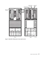
Page 283: ...Figure 1b Model 840 SB3 processor tower dual line cord Analyze hardware problems 271...
Page 294: ...01 gif port and LED locations 282 Hardware Remove and Replace Part Locations and Listings...
Page 295: ...s src rzaq4519 gif locations Analyze hardware problems 283...
Page 483: ...Table 1 Cover assembly FC 5095 Expansion I O Tower Analyze hardware problems 471...
Page 614: ...602 Hardware Remove and Replace Part Locations and Listings...
Page 618: ...606 Hardware Remove and Replace Part Locations and Listings...
Page 621: ......
Page 622: ...Printed in USA SY44 5917 02...

