


Note:
Both
ends
of
the
ribbon
cables
are
marked
LH
or
RH
,
indicating
that
one
end
of
the
cable
is
plugged
in
to
either
the
left-hand
(DB1)
or
right-hand
(DB2)
DASD
board
assembly.
The
other
end
of
the
cable
is
plugged
in
to
either
the
left-most
(LH)
or
right-most
(RH)
DASD
controller
card.
The
cables
will
crisscross
in
the
center
of
the
tower.
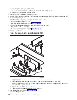
c.
Remove
the
screws
that
hold
the
tower
card
enclosure
to
the
frame.
d.
Pull
the
tower
card
enclosure
partially
out
of
the
frame
while
lifting
the
cables
clear
of
the
enclosure.
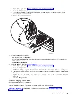
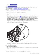
e.
Press
the
release
mechanism
that
is
located
along
the
top
right
side
of
the
enclosure
and
carefully
slide
the
enclosure
towards
you.
Make
sure
that
the
cables
are
clear
of
the
enclosure.
f.
Remove
the
tower
card
enclosure
from
the
frame.
g.
Remove
the
screws
from
the
EMC
access
plate
that
is
located
inside
the
frame
and
directly
above
the
power
distribution
board.
h.
Remove
the
EMC
access
plate.
i.
Reach
through
the
opening
and
remove
the
cables
from
the
backside
of
the
base
DASD
board
assembly
(DB3).
5.
Open
the
front
cover.
See
6.
From
the
front
of
the
expansion
tower
do
the
following:
a.
Note
the
removable
media
locations
and
then
remove
them
by
pulling
out
on
the
handles
that
are
located
on
each
side
of
the
unit.
b.
Remove
the
control
panel
by
pulling
on
the
handles
that
are
located
on
each
side
of
the
unit
and
sliding
it
partially
out
of
the
tower.
Then,
unplug
the
cable
from
the
rear
of
the
control
panel.
(See
c.
Unplug
the
control
panel
cable
from
the
base
DASD
board
assembly
(DB3).
d.
Remove
the
two
retaining
screws
that
are
located
inside
of
the
removable
media
enclosure
(the
top
right
and
lower
left
corners).
e.
Remove
the
removable
media
enclosure.
f.
Remove
the
EMC
access
plates
from
the
disk
unit
enclosures
that
are
located
in
front
of
the
backplane
(DB3).
For
location
information,
see
Press
the
surfaces
of
the
two
latching
mechanisms
together
and
tilt
the
top
of
the
cover
away
from
the
frame
to
remove
it.
g.
Record
the
disk
unit
locations
and
then
remove
them
from
the
disk
unit
enclosures
that
you
just
uncovered.
Attention:
The
disk
units
are
sensitive
to
electrostatic
discharge
(see
h.
Remove
the
screws
that
hold
the
disk
unit
enclosures
to
the
frame.
i.
Remove
the
retaining
screws
that
are
located
inside
the
disk
unit
enclosure.
j.
Remove
the
disk
unit
enclosures.
k.
Remove
the
screws
that
hold
the
center
support
bracket
and
shelf
for
the
disk
unit
and
removable
media
enclosure
to
the
frame.
l.
Remove
the
support
bracket
and
shelf.
m.
Remove
the
base
DASD
board
assembly
(DB3).
7.
Install
the
base
DASD
board
assembly
by
reversing
the
removal
procedure.
After
exchanging
an
item,
go
to
This
ends
the
procedure.
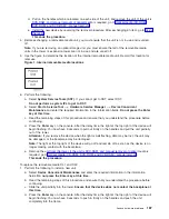
FC
5094,
FC
9094
-
Disk
unit
(concurrent)
For
use
by
authorized
service
providers.
Use
this
procedure
to
remove
or
replace
a
disk
unit
using
concurrent
maintenance
in
an
FC
5094,
or
FC
9094.
180
Hardware
(Remove
and
Replace;
Part
Locations
and
Listings)
Summary of Contents for 270
Page 2: ......
Page 12: ...x Hardware Remove and Replace Part Locations and Listings...
Page 279: ...Figure 3 CCIN 2881 with pluggable DIMM Analyze hardware problems 267...
Page 281: ...Figure 6 Models 830 SB2 with FC 9074 HSL and SPCN locations Analyze hardware problems 269...
Page 283: ...Figure 1b Model 840 SB3 processor tower dual line cord Analyze hardware problems 271...
Page 294: ...01 gif port and LED locations 282 Hardware Remove and Replace Part Locations and Listings...
Page 295: ...s src rzaq4519 gif locations Analyze hardware problems 283...
Page 483: ...Table 1 Cover assembly FC 5095 Expansion I O Tower Analyze hardware problems 471...
Page 614: ...602 Hardware Remove and Replace Part Locations and Listings...
Page 618: ...606 Hardware Remove and Replace Part Locations and Listings...
Page 621: ......
Page 622: ...Printed in USA SY44 5917 02...


