


v
Yes
:
Replace
the
covers
that
were
removed
during
this
procedure
and
return
to
the
procedure
that
sent
you
here.
This
ends
the
procedure.
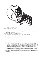
6.
Install
the
disk
unit
by
performing
the
following:
a.
Power
off
the
system
(see
b.
Disconnect
the
power
cord.
c.
Put
the
disk
unit
part
way
into
the
desired
slot
and
rotate
the
handle
of
the
disk
unit
towards
you.
d.
Push
the
disk
unit
completely
into
the
slot
and
rotate
the
handle
towards
the
disk
unit
to
latch
it
into
the
slot.
e.
Replace
the
covers
that
were
removed
during
this
procedure
and
return
to
the
procedure
that
sent
you
here.
This
ends
the
procedure.
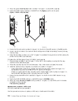
FC
5074,
FC
5079
-
Display
panel
-
NB1
For
use
by
authorized
service
providers.
Use
this
procedure
to
remove
or
replace
the
display
panel
-
NB1
in
an
FC
5074
or
FC
5079.
Attention:
The
display
panel
is
sensitive
to
electrostatic
discharge
(see
To
remove
or
replace
the
display
panel
-
NB1:
1.
Power
off
the
expansion
tower.
See
the
2.
Disconnect
the
ac
power
cord
from
the
expansion
tower.
3.
Open
the
front
cover.
See
4.
Pull
on
the
two
side
fasteners
to
release
the
display
panel
assembly.
5.
Slide
the
panel
partially
out
of
the
frame.
6.
Disconnect
the
cables
that
are
attached
to
the
backside
of
the
display
panel.
7.
Remove
the
display
panel
from
the
frame.
8.
Reverse
the
above
procedure
to
install
the
new
panel.
9.
After
exchanging
an
item,
go
to
This
ends
the
procedure.
FC
5074,
FC
5079,
FC
9079
-
Power
distribution
board
-
PB1
For
use
by
authorized
service
providers.
Use
this
procedure
to
remove
or
replace
the
power
distribution
board
-
PB1
in
an
FC
5074,
FC
5079,
or
FC
9079.
To
remove
or
replace
the
power
distribution
board
-
PB1:
1.
You
must
remove
both
disk
unit
backplanes
(DB1
and
DB2).
Perform
for
each
backplane.
Continue
with
the
next
step.
2.
From
the
rear
of
the
expansion
tower,
do
the
following:
a.
Open
the
rear
cover.
See
b.
Remove
the
EMC
access
plate
that
is
located
directly
above
the
PCI
card
enclosure.
Press
the
surfaces
of
the
two
latching
mechanisms
together
and
tilt
the
top
of
the
cover
away
from
the
frame
to
remove
it.
c.
Remove
the
cables
from
the
disk
unit
controller
cards
that
are
located
inside
the
PCI
card
enclosure.
Attention:
All
cards
are
sensitive
to
electrostatic
discharge
(see
148
Hardware
(Remove
and
Replace;
Part
Locations
and
Listings)
Summary of Contents for 270
Page 2: ......
Page 12: ...x Hardware Remove and Replace Part Locations and Listings...
Page 279: ...Figure 3 CCIN 2881 with pluggable DIMM Analyze hardware problems 267...
Page 281: ...Figure 6 Models 830 SB2 with FC 9074 HSL and SPCN locations Analyze hardware problems 269...
Page 283: ...Figure 1b Model 840 SB3 processor tower dual line cord Analyze hardware problems 271...
Page 294: ...01 gif port and LED locations 282 Hardware Remove and Replace Part Locations and Listings...
Page 295: ...s src rzaq4519 gif locations Analyze hardware problems 283...
Page 483: ...Table 1 Cover assembly FC 5095 Expansion I O Tower Analyze hardware problems 471...
Page 614: ...602 Hardware Remove and Replace Part Locations and Listings...
Page 618: ...606 Hardware Remove and Replace Part Locations and Listings...
Page 621: ......
Page 622: ...Printed in USA SY44 5917 02...


