v
The
right
column
is
used
to
determine
the
IOP
to
which
an
IOA
is
assigned.
v
The
first
position
in
the
list
must
be
an
IOP.
The
remaining
positions
may
be
IOPs
or
IOAs.
IOAs
are
assigned
to
the
first
IOP
located
to
their
left
in
the
list.
Although
IOAs
can
be
manually
reassigned
using
SST/DST,
the
IOA
assignments
return
to
the
default
order
after
each
IPL.
Table
2.
IOA
assignment
rules
Multi-adapter
bridge
domain
/
PCI
bridge
set
IOA
assignment
rules
C01
-
C04
C01,
C02,
C03,
C04
C05
-
C10
(Not
including
C08)
C05,
C06,
C07,
C09,
C10
C11
-
C15
C11,
C12,
C13,
C14,
C15
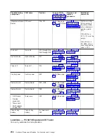
Locations
-
FC
5079
Expansion
I/O
Tower
For
use
by
authorized
service
providers.
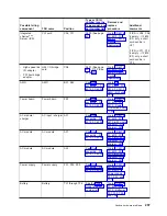
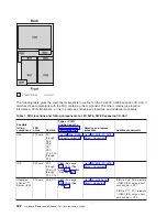
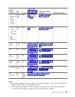
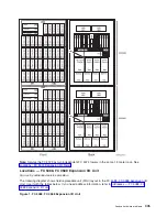
The
following
diagram
shows
field
replaceable
unit
(FRU)
layout
in
the
FC
5079
Expansion
I/O
Tower.
Use
it
with
the
information
that
follows.
If
you
need
address
information,
refer
to
Figure
1.
Locations
for
FC
5079
Expansion
I/O
Tower
304
Hardware
(Remove
and
Replace;
Part
Locations
and
Listings)
Summary of Contents for 270
Page 2: ......
Page 12: ...x Hardware Remove and Replace Part Locations and Listings...
Page 279: ...Figure 3 CCIN 2881 with pluggable DIMM Analyze hardware problems 267...
Page 281: ...Figure 6 Models 830 SB2 with FC 9074 HSL and SPCN locations Analyze hardware problems 269...
Page 283: ...Figure 1b Model 840 SB3 processor tower dual line cord Analyze hardware problems 271...
Page 294: ...01 gif port and LED locations 282 Hardware Remove and Replace Part Locations and Listings...
Page 295: ...s src rzaq4519 gif locations Analyze hardware problems 283...
Page 483: ...Table 1 Cover assembly FC 5095 Expansion I O Tower Analyze hardware problems 471...
Page 614: ...602 Hardware Remove and Replace Part Locations and Listings...
Page 618: ...606 Hardware Remove and Replace Part Locations and Listings...
Page 621: ......
Page 622: ...Printed in USA SY44 5917 02...


