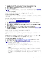
7.
Remove
the
control
panel
from
the
frame.
8.
Loosen
the
two
screws
that
retain
the
processor
capacity
card
retention
(back)
cover
and
remove
the
cover.
9.
If
you
are
replacing
the
panel,
then
you
must
move
the
processor
capacity
card
and
interactive
card
to
the
new
panel.
Important:
Mark
the
processor
capacity
card
and
interactive
cards
as
to
their
positions
and
orientation,
then
remove
the
cards.
See
10.
Install
the
processor
capacity
card
and
Interactive
cards
into
the
new
panel
and
replace
the
retention
cover.
11.
Remove
the
plastic
tab
on
the
front
of
the
control
panel
that
has
the
machine
type
and
serial
number.
The
tab
should
then
be
installed
onto
the
new
control
panel.
12.
Reverse
the
above
procedure
to
install
the
panel.
Note:
When
a
control
panel
with
keystick
is
replaced,
discard
the
new
keysticks
that
come
with
the
panel
and
reuse
the
original
keysticks.
13.
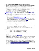
If
you
are
here
to
replace
the
processor
capacity
card
or
interactive
card,
then
replace
only
that
card
and
not
the
panel.
Are
you
replacing
the
processor
capacity
card?
v
Yes
:
Continue
with
the
next
step.
v
No
:
If
you
are
replacing
the
interactive
card,
continue
with
step
18
(See
page
14.
If
you
are
here
to
replace
a
processor
capacity
card
that
was
associated
with
processor-on-demand
(POD)
processor
features,
perform
the
following:
a.
Contact
your
second
level
of
support
to
determine
if
a
POD
activation
code
is
required
to
reset
previously
activated
on-demand
processors.
b.
If
necessary,
a
new
POD
activation
code
will
need
to
be
generated
and
then
entered
at
the
server.
c.
After
entering
a
POD
activation
code,
30
minutes
should
elapse
before
an
IPL
is
performed
to
ensure
the
POD
activation
code
has
been
saved.
Note:
DST/SST
options
to
activate
POD
will
not
be
visible
if
the
system
password
has
been
bypassed.
15.
Does
the
system
that
you
are
working
on
have
a
keystick
lock?
v
Yes
:
Continue
with
the
next
step.
v
No
:
Go
to
step
18
(See
page
16.
Do
you
have
the
original
system
unit
keys
and
are
you
reusing
them?
v
No
:
Continue
with
the
next
step.
v
Yes
:
Go
to
step
18
(See
page
17.
Perform
the
following:
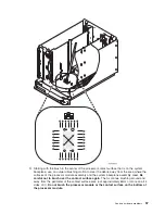
Figure
1.
System
unit
control
panel
with
keystick
(NB1)
Analyze
hardware
problems
65
Summary of Contents for 270
Page 2: ......
Page 12: ...x Hardware Remove and Replace Part Locations and Listings...
Page 279: ...Figure 3 CCIN 2881 with pluggable DIMM Analyze hardware problems 267...
Page 281: ...Figure 6 Models 830 SB2 with FC 9074 HSL and SPCN locations Analyze hardware problems 269...
Page 283: ...Figure 1b Model 840 SB3 processor tower dual line cord Analyze hardware problems 271...
Page 294: ...01 gif port and LED locations 282 Hardware Remove and Replace Part Locations and Listings...
Page 295: ...s src rzaq4519 gif locations Analyze hardware problems 283...
Page 483: ...Table 1 Cover assembly FC 5095 Expansion I O Tower Analyze hardware problems 471...
Page 614: ...602 Hardware Remove and Replace Part Locations and Listings...
Page 618: ...606 Hardware Remove and Replace Part Locations and Listings...
Page 621: ......
Page 622: ...Printed in USA SY44 5917 02...

