Models
270,
800,
and
810
-
Cards
(dedicated)
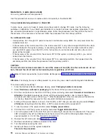
For
use
by
authorized
service
providers.
Use
this
procedure
to
remove
or
replace
cards
using
dedicated
maintenance
on
the
Models
270,
800,
and
810.
The
Models
270,
800,
and
810
may
be
housed
in
a
FC
0551
frame.
The
upper
and
lower
system
units
are
placed
on
rails
in
the
frame.
If
you
are
working
on
the
upper
or
lower
unit
in
a
0551
frame,
follow
these
instructions
and
access
the
internal
parts
by
opening
the
front
cover
and
sliding
the
system
unit
out
on
its
rails.
In
some
cases
for
the
Models
270
and
810,
you
do
not
need
to
power
down
the
system
to
change
PCI
cards.
Use
the
guidelines
in
to
determine
if
you
should
use
dedicated
or
concurrent
remove
and
replace
procedures.
CAUTION:
The
circuit
card
contains
lead
solder.
To
avoid
the
release
of
lead
(Pb)
into
the
environment,
do
not
burn.
Discard
the
circuit
card
as
instructed
by
local
regulations.
(RSFTC234)
Attention:
All
cards
are
sensitive
to
electrostatic
discharge.
See
To
remove
or
replace
cards
(dedicated):
1.
Power
off
the
system.
See
2.
Remove
the
ac
power
cord
on
the
frame
you
are
working
on.
On
Models
270,
800,
and
810
with
a
system
unit
expansion
attached,
disconnect
both
the
system
line
cord
and
the
expansion
unit
line
cord.
3.
Remove
the
left
side
cover.
See
4.
Are
you
removing
a
memory
DIMM?
v
Yes
:
Press
down
on
the
latches
that
are
located
on
each
side
of
the
memory
DIMM
to
release
it
from
the
backplane.
This
ends
the
procedure.
v
No
:
Remove
and
label
any
cables
connected
to
the
card.
5.
Either
turn
the
latches
securing
the
card
or
unscrew
the
bracket
securing
the
card.
6.
Gently
pull
the
card
off
the
system
backplane.
7.
Reverse
this
procedure
to
replace
the
card.
Note:
If
you
have
exchanged
a
2766
or
2787
Fibre
Channel
IOA,
the
IBM
2105
disk
unit
subsystem
must
be
updated
to
use
the
World-Wide
Port-Name
of
the
new
2766
or
2787
IOA.
This
name
can
be
found
in
the
Port
worldwide
name
field
on
the
iSeries
by
displaying
detail
on
the
2766
or
2787
IOA
Logical
Hardware
Resource
information
in
Hardware
Service
Manager
in
SST
or
DST.
The
16-digit
World-Wide
Port-Name
can
also
be
determined
by
appending
the
digits
″
1000
″
to
the
beginning
of
the
12-digit
IEEE
Address
found
on
the
tailstock
label
of
the
Fibre
Channel
IOA.
Use
the
ESS
Web
Interface
User’s
Guide
(SC26-7346)
to
update
the
World-Wide
Port-Name
in
the
host
configuration
on
the
IBM
2105
ESS.
The
ESS
Web
Interface
User’s
Guide
can
also
be
found
at
the
following
URL:
http://ssddom02.storage.ibm.com/disk/ess/documentation.html
This
ends
the
procedure.
Models
270,
800,
and
810
-
Control
panel
-
NB1
For
use
by
authorized
service
providers.
Use
this
procedure
to
remove
or
install
the
control
panel
-
NB1
on
Models
270,
800,
and
810.
6
Hardware
(Remove
and
Replace;
Part
Locations
and
Listings)
Summary of Contents for 270
Page 2: ......
Page 12: ...x Hardware Remove and Replace Part Locations and Listings...
Page 279: ...Figure 3 CCIN 2881 with pluggable DIMM Analyze hardware problems 267...
Page 281: ...Figure 6 Models 830 SB2 with FC 9074 HSL and SPCN locations Analyze hardware problems 269...
Page 283: ...Figure 1b Model 840 SB3 processor tower dual line cord Analyze hardware problems 271...
Page 294: ...01 gif port and LED locations 282 Hardware Remove and Replace Part Locations and Listings...
Page 295: ...s src rzaq4519 gif locations Analyze hardware problems 283...
Page 483: ...Table 1 Cover assembly FC 5095 Expansion I O Tower Analyze hardware problems 471...
Page 614: ...602 Hardware Remove and Replace Part Locations and Listings...
Page 618: ...606 Hardware Remove and Replace Part Locations and Listings...
Page 621: ......
Page 622: ...Printed in USA SY44 5917 02...


