
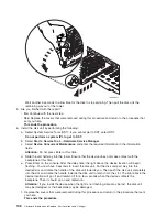


3.
After
you
have
determined
the
location
of
the
disk
unit
to
replace,
remove
the
front
covers
for
access.
See
4.
Remove
the
EMC
access
plate
that
is
over
the
location
of
the
disk
unit
that
you
are
removing.
For
location
information,
see
5.
To
remove
a
disk
unit
using
concurrent
maintenance
perform
the
following:
a.
Select
System
Service
Tools
(SST).
If
you
cannot
get
to
SST,
select
DST.
Do
not
perform
a
system
IPL
to
get
to
DST.
b.
Select
Start
a
Service
Tool
—>
Hardware
Service
Manager
.
c.
Select
Device
Concurrent
Maintenance
and
enter
the
required
information
in
the
information
fields.
d.
Press
Enter
on
the
console.
After
the
delay
time,
the
light
above
the
device
location
will
begin
flashing.
You
now
have
9
seconds
to
pinch
the
two
surfaces
of
the
latching
mechanism
together
and
rotate
the
handle
of
the
disk
unit
towards
you.
Pull
the
disk
unit
partially
out
of
the
tower.
The
light
above
the
device
location
will
go
off
and
remain
off
as
soon
as
the
device
is
no
longer
making
contact
with
the
backplane.
Attention:
If
you
remove
the
device
when
the
light
is
not
flashing,
data
may
be
lost,
the
disk
unit
may
be
damaged,
or
the
backplane
may
be
damaged.
Wait
another
5
seconds
to
allow
time
for
the
disk
to
stop
spinning.
Then
pull
the
disk
unit
the
remaining
way
out
of
the
tower.
6.
Are
you
finished
with
the
repair?
v
No
:
Continue
with
the
next
step.
v
Yes
:
Replace
the
covers
that
were
removed
during
this
procedure
and
return
to
the
procedure
that
sent
you
here.
This
ends
the
procedure.
7.
To
install
a
disk
unit
using
concurrent
maintenance
perform
the
following:
a.
Select
System
Service
Tools
(SST).
If
you
cannot
get
to
SST,
select
DST.
Do
not
perform
a
system
IPL
to
get
to
DST.
Analyze
hardware
problems
159
Summary of Contents for 270
Page 2: ......
Page 12: ...x Hardware Remove and Replace Part Locations and Listings...
Page 279: ...Figure 3 CCIN 2881 with pluggable DIMM Analyze hardware problems 267...
Page 281: ...Figure 6 Models 830 SB2 with FC 9074 HSL and SPCN locations Analyze hardware problems 269...
Page 283: ...Figure 1b Model 840 SB3 processor tower dual line cord Analyze hardware problems 271...
Page 294: ...01 gif port and LED locations 282 Hardware Remove and Replace Part Locations and Listings...
Page 295: ...s src rzaq4519 gif locations Analyze hardware problems 283...
Page 483: ...Table 1 Cover assembly FC 5095 Expansion I O Tower Analyze hardware problems 471...
Page 614: ...602 Hardware Remove and Replace Part Locations and Listings...
Page 618: ...606 Hardware Remove and Replace Part Locations and Listings...
Page 621: ......
Page 622: ...Printed in USA SY44 5917 02...


