


11.
Record
on
the
log
sheet
on
the
system
the
date
that
this
L3
has
been
removed.
To
return
L3
modules:
The
following
procedure
provides
handling
instructions
for
L3
modules
to
be
packaged
and
returned
to
the
plant
of
manufacture.
1.
If
you
are
replacing
an
L3
module,
use
the
packaging
from
the
new
module
to
return
the
old
module.
If
the
packaging
is
not
available,
or
does
not
include
all
the
parts
described
below,
order
the
following
part
for
L3
module
protective
packaging:
One
L3
protective
package
(PN
7335692)
which
includes:
v
One
carton
v
One
top
foam
cushion
v
One
bottom
foam
cushion
with
four
cavities
v
One
ESD
bag
v
One
desiccant
2.
Place
the
bottom
foam
cushion,
wrapped
with
ESD
bag,
inside
the
corrugated
carton.
Leaving
the
ESD
bag
open,
place
the
L3
module
with
the
cover
into
the
bottom
cushion,
heat
sink
down.
This
will
fit
snugly
into
the
cavity
of
the
foam.
3.
Add
the
desiccant
and
seal
the
ESD
bag
with
tape.
(The
desiccant
is
optional
for
returned
parts).
4.
Place
the
top
foam
cushion
over
the
assembly
inside
the
carton.
5.
Seal
the
carton
and
ship.
To
install
L3
modules:
1.
Go
to
the
Testing
L3
cache
modules
for
a
short
circuit
(See
page
page
and
install
the
L3
module
short-circuit
test
tool.
Use
the
test
tool
during
the
L3
cache
module
replacement
procedure
to
ensure
that
the
L3
cache
modules
are
installed
without
a
short
circuit.
If
you
install
an
L3
cache
module
and
encounter
a
short
circuit,
the
L3
cache
you
installed
must
be
replaced.
2.
If
installing
a
new
L3
module,
perform
a
general
cleaning
operation,
using
a
sash
brush,
part
number
450732
(not
the
one
included
with
the
FRU
kit)
and
vacuum
cleaner
to
remove
any
accumulated
dust
and
debris
that
has
settled
in
the
processor
subsystem.
Hold
the
vacuum
hose
near
the
brush
to
remove
any
debris
the
brush
generates,
then
remove
the
L3
filler
from
the
site
where
the
new
L3
is
to
be
located.
3.
Follow
the
procedure
described
in
the
Attention
note
below
to
clean
the
LGA
site
using
the
brush
supplied
with
the
new
module.
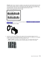
Note:
Before
you
remove
the
brush
from
its
protective
bag,
loosen
the
bristles
by
pressing
them
on
the
ESD
mat
until
they
are
90
degrees
from
the
handle.
102
Hardware
(Remove
and
Replace;
Part
Locations
and
Listings)
Summary of Contents for 270
Page 2: ......
Page 12: ...x Hardware Remove and Replace Part Locations and Listings...
Page 279: ...Figure 3 CCIN 2881 with pluggable DIMM Analyze hardware problems 267...
Page 281: ...Figure 6 Models 830 SB2 with FC 9074 HSL and SPCN locations Analyze hardware problems 269...
Page 283: ...Figure 1b Model 840 SB3 processor tower dual line cord Analyze hardware problems 271...
Page 294: ...01 gif port and LED locations 282 Hardware Remove and Replace Part Locations and Listings...
Page 295: ...s src rzaq4519 gif locations Analyze hardware problems 283...
Page 483: ...Table 1 Cover assembly FC 5095 Expansion I O Tower Analyze hardware problems 471...
Page 614: ...602 Hardware Remove and Replace Part Locations and Listings...
Page 618: ...606 Hardware Remove and Replace Part Locations and Listings...
Page 621: ......
Page 622: ...Printed in USA SY44 5917 02...


