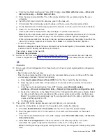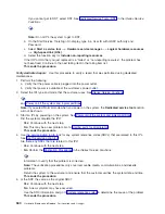
e.
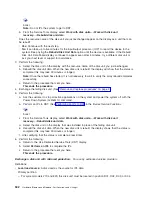
If
you
have
a
system
with
only
one
disk
unit,
a
message
may
appear
stating
that
your
request
to
recover
the
configuration
was
not
successful.
The
recover
configuration
function
cannot
be
performed
on
a
system
with
only
one
disk
unit.
Go
to
step
15
(See
page
f.
Otherwise,
go
to
step
16
(See
page
15.
Because
the
disk
data
was
not
recoverable,
clear
the
auxiliary
storage
pool
(ASP)
to
which
the
disk
unit
is
assigned
by
doing
the
following:
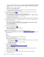
a.
Return
to
the
Work
with
Disk
Units
display.
Select
Work
with
disk
configuration
—>
Work
with
ASP
configuration
—>
Delete
ASP
data
.
b.
Enter
the
Delete
option
for
the
ASP
that
you
recorded
in
step
3
(See
page
c.
Confirm
the
Delete
ASP
Data.
d.
Return
to
the
Work
with
Disk
Units
display,
and
select
Work
with
disk
unit
recovery
—>
Replace
configured
unit
.
e.
On
the
Select
Configured
Unit
to
Replace
display,
select
the
configured
disk
unit
to
exchange.
f.
On
the
Select
Replacement
Unit
display,
select
the
new
disk
unit.
g.
Press
Enter
to
confirm
the
replace
operation
(this
operation
takes
10
to
15
minutes
to
complete).
Attention:
The
auxiliary
storage
pool
to
which
the
disk
unit
is
assigned
was
erased.
The
customer
must
restore
the
data
to
the
auxiliary
storage
pool
(have
the
customer
see
the
Backup
and
Recovery
information).
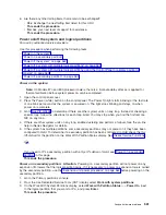
16.
The
ASP
to
which
the
failing
disk
unit
was
assigned
was
erased.
The
customer
should
do
the
following:
v
If
the
disk
unit
you
exchanged
is
in
ASP
1,
have
the
customer
see
the
Backup
and
Recovery
information
to
restore
the
operating
system
(OS/400
Licensed
Program)
and
all
customer
data.
v
If
the
disk
unit
is
in
a
user
ASP
(ASP
2
through
ASP
16),
data
in
the
ASP
is
lost.
See
the
Backup
and
Recovery
information.
This
ends
the
procedure.
17.
The
remaining
steps
of
this
procedure
require
a
dedicated
system.
Have
the
customer
do
a
normal
power-off
procedure
of
the
system.
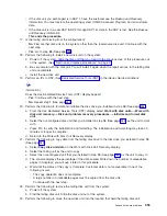
18.
Perform
an
IPL
to
DST.
See
in
the
iSeries
Service
Functions
information.
Is
the
IPL
or
Install
the
System
display
shown,
or
is
DST
available?
v
No
:
Go
to
step
2
(See
page
v
Yes
:
Select
Use
dedicated
service
tools
(DST)
on
the
display
or
use
a
function
key.
You
need
the
customer
password
to
get
to
the
Use
Dedicated
Service
Tools
(DST)
display.
Continue
with
the
next
step.
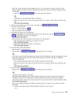
19.
Perform
the
following:
a.
From
the
Use
Dedicated
Service
Tools
(DST)
display,
select
Work
with
disk
units
—>
Work
with
disk
configuration
—>
Display
disk
configuration
—>
Display
disk
configuration
status
.
b.
Record
the
ASP,
unit,
serial
number,
type,
and
resource
name
of
the
disk
unit.
c.
On
the
Display
Disk
Configuration
Status
display,
ensure
the
following:
v
The
disk
unit
is
not
the
load-source
disk
unit
(disk
unit
1).
v
No
disk
units
are
missing
from
the
configuration.
Note:
An
asterisk
(*)
next
to
the
unit
number
indicates
a
missing
unit.
v
The
status
field
of
the
disk
unit
to
be
removed
shows
Configured
.
Are
all
these
conditions
true?
v
Yes
:
Continue
with
the
next
step.
v
No
:
You
cannot
use
the
Remove
Units
from
Configuration
function.
Go
to
step
2
(See
page
550
Hardware
(Remove
and
Replace;
Part
Locations
and
Listings)
Summary of Contents for 270
Page 2: ......
Page 12: ...x Hardware Remove and Replace Part Locations and Listings...
Page 279: ...Figure 3 CCIN 2881 with pluggable DIMM Analyze hardware problems 267...
Page 281: ...Figure 6 Models 830 SB2 with FC 9074 HSL and SPCN locations Analyze hardware problems 269...
Page 283: ...Figure 1b Model 840 SB3 processor tower dual line cord Analyze hardware problems 271...
Page 294: ...01 gif port and LED locations 282 Hardware Remove and Replace Part Locations and Listings...
Page 295: ...s src rzaq4519 gif locations Analyze hardware problems 283...
Page 483: ...Table 1 Cover assembly FC 5095 Expansion I O Tower Analyze hardware problems 471...
Page 614: ...602 Hardware Remove and Replace Part Locations and Listings...
Page 618: ...606 Hardware Remove and Replace Part Locations and Listings...
Page 621: ......
Page 622: ...Printed in USA SY44 5917 02...

