


into
the
slot
and
rotate
the
handle
towards
the
disk
unit
to
latch
it
into
the
slot.
The
light
above
the
device
location
will
go
off
and
remain
off
for
a
few
seconds
when
the
device
contacts
the
backplane.
Then
it
should
go
on
and
remain
on.
Attention:
If
you
install
the
device
when
the
light
is
not
flashing,
data
may
be
lost,
the
disk
unit
may
be
damaged,
or
the
backplane
may
be
damaged.
f.
Replace
the
covers
that
were
removed
during
this
procedure
and
return
to
the
procedure
that
sent
you
here.
This
ends
the
procedure.
Dedicated
maintenance
-
Remove
and
replace
1.
To
remove
a
disk
unit
using
dedicated
maintenance
perform
the
following:
a.
Power
off
the
system.
See
b.
Disconnect
the
power
cord.
c.
To
remove
the
disk
unit,
pinch
the
two
surfaces
of
the
latching
mechanism
together
and
pull
the
handle
towards
you
to
release
the
disk
unit
from
the
slot.
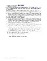
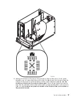
d.
Remove
the
unit.
See
Figure
1.
Disk
unit
removal,
Models
830/SB2
and
840/SB3
(concurrent)
(See
page
above.
2.
Are
you
finished
with
the
repair?
v
No
:
Continue
with
the
next
step.
v
Yes
:
Replace
the
covers
that
were
removed
during
this
procedure
and
return
to
the
procedure
that
sent
you
here.
This
ends
the
procedure.
3.
To
install
a
disk
unit
using
dedicated
maintenance
perform
the
following:
a.
Power
off
the
system.
See
b.
Disconnect
the
power
cord.
c.
Put
the
disk
unit
part
way
into
the
desired
slot
and
rotate
the
handle
of
the
disk
unit
towards
you.
d.
Push
the
disk
unit
completely
into
the
slot
and
rotate
the
handle
towards
the
disk
unit
to
latch
it
into
the
slot.
e.
Replace
the
covers
that
were
removed
during
this
procedure
and
return
to
the
procedure
that
sent
you
here.
This
ends
the
procedure.
Models
830/SB2
with
FC
9074
-
System
unit
control
panel
(NB1)
For
use
by
authorized
service
providers.
Use
this
procedure
to
remove
or
replace
the
control
panel
-
NB1
on
Models
830/SB2
with
FC
9074.
Attention:
The
control
panel
including
the
processor
capacity
card
and
interactive
cards
are
sensitive
to
electrostatic
discharge
(see
CAUTION:
The
circuit
card
contains
lead
solder.
To
avoid
the
release
of
lead
(Pb)
into
the
environment,
do
not
burn.
Discard
the
circuit
card
as
instructed
by
local
regulations.
(RSFTC234)
To
remove
or
replace
the
control
panel
(NB1):
1.
Power
off
the
system.
See
2.
Disconnect
the
ac
power
cord
from
the
system
unit.
3.
Open
the
front
cover.
See
4.
Pull
on
the
two
side
fasteners
to
release
the
control
panel
assembly.
5.
Slide
the
panel
partially
out
of
the
frame.
6.
Disconnect
the
cables
that
are
attached
to
backside
of
the
control
panel.
64
Hardware
(Remove
and
Replace;
Part
Locations
and
Listings)
Summary of Contents for 270
Page 2: ......
Page 12: ...x Hardware Remove and Replace Part Locations and Listings...
Page 279: ...Figure 3 CCIN 2881 with pluggable DIMM Analyze hardware problems 267...
Page 281: ...Figure 6 Models 830 SB2 with FC 9074 HSL and SPCN locations Analyze hardware problems 269...
Page 283: ...Figure 1b Model 840 SB3 processor tower dual line cord Analyze hardware problems 271...
Page 294: ...01 gif port and LED locations 282 Hardware Remove and Replace Part Locations and Listings...
Page 295: ...s src rzaq4519 gif locations Analyze hardware problems 283...
Page 483: ...Table 1 Cover assembly FC 5095 Expansion I O Tower Analyze hardware problems 471...
Page 614: ...602 Hardware Remove and Replace Part Locations and Listings...
Page 618: ...606 Hardware Remove and Replace Part Locations and Listings...
Page 621: ......
Page 622: ...Printed in USA SY44 5917 02...


