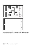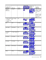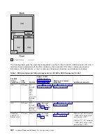
The
letters
in
Figure
3
give
the
VPD
card
placement
for
the
system.
The
letters
correlate
to
the
following
cards:
v
A
=
Processor
capacity
card
v
B
=
Interactive
card
v
C
=
L3
VPD
card
v
D
=
VPD
for
MCM
0
in
location
M21
v
E
=
VPD
for
MCM
2
in
location
M11
v
F
=
VPD
for
MCM
1
in
location
M16
v
G
=
VPD
for
MCM
3
in
location
M14
Note:
MCMs
and
their
associated
VPD
card
in
location
M41
have
the
same
serial
number
and
must
always
be
kept
together.
That
is,
you
cannot
swap
MCM
VPD
cards
between
slots
or
between
systems.
Figure
4.
VPD
card
placement
on
the
Network
Interface
Controller
(NIC)
card
(Location
M41)
Analyze
hardware
problems
287
Summary of Contents for 270
Page 2: ......
Page 12: ...x Hardware Remove and Replace Part Locations and Listings...
Page 279: ...Figure 3 CCIN 2881 with pluggable DIMM Analyze hardware problems 267...
Page 281: ...Figure 6 Models 830 SB2 with FC 9074 HSL and SPCN locations Analyze hardware problems 269...
Page 283: ...Figure 1b Model 840 SB3 processor tower dual line cord Analyze hardware problems 271...
Page 294: ...01 gif port and LED locations 282 Hardware Remove and Replace Part Locations and Listings...
Page 295: ...s src rzaq4519 gif locations Analyze hardware problems 283...
Page 483: ...Table 1 Cover assembly FC 5095 Expansion I O Tower Analyze hardware problems 471...
Page 614: ...602 Hardware Remove and Replace Part Locations and Listings...
Page 618: ...606 Hardware Remove and Replace Part Locations and Listings...
Page 621: ......
Page 622: ...Printed in USA SY44 5917 02...


