


3.
Unplug
the
power
supply
cable.
Refer
to
and
continue
with
the
following
steps.
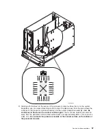
4.
Remove
the
mounting
screw
from
the
power
supply.
5.
Rotate
the
handle
from
left
to
right
to
release
the
power
supply
from
the
frame.
6.
Remove
the
power
supply.
7.
Install
the
new
power
supply
by
reversing
the
removal
procedure.
Note:
Do
not
slam
the
new
power
supply
when
installing
it
into
the
system.
Insert
the
power
supply
until
it
engages
the
frame,
then
rotate
the
handle
from
right
to
left.
8.
After
exchanging
an
item,
go
to
This
ends
the
procedure.
Model
830/SB2
-
Processor
feature
codes
and
CCINs
For
use
by
authorized
service
providers.
The
processor
cards
in
this
system
can
only
be
attached
to
the
backplane
once.
If
a
processor
card
is
removed,
it
must
be
replaced
with
a
new
processor
card.
Perform
the
following:
1.
Use
control
panel
function
20
to
determine
the
processor
feature
code
(if
it
has
not
already
been
determined).
2.
Use
the
table
below
to
determine
the
CCIN
and
location
for
the
processor
cards.
3.
Use
the
CCIN
in
conjunction
with
the
to
obtain
the
part
numbers
for
the
processors
that
you
will
need
to
replace.
4.
Refer
to
and
for
the
appropriate
remove
and
replace
procedure.
Table
1.
Model
830/SB2
-
Processor
CCIN
System
model
Processor
feature
code
Processor
CCIN
Processor
location
830
(2-way)
23C1,
23C2,
23C3,
23C4,
23C5
245C
M03
830
(4-way)
23D1,
23D2,
23D3,
23D4,
23D5,
23D6
245D
M03
830
(8-way)
23D8,
23D9,
23DA,
23DB,
23DC,
23DD,
23DE
245D
(You
will
need
a
quantity
of
two.)
M03,
M04
SB2
(8-way)
2315
245D
(You
will
need
a
quantity
of
two.)
M03,
M04
Models
830/SB2
with
FC
9074
-
Removable
media
(D41
and
D42)
For
use
by
authorized
service
providers.
Use
this
procedure
to
remove
or
replace
removable
media
(D41
and
D42)
on
Models
830/SB2
with
FC
9074.
Laser
safety
information:
CAUTION:
This
product
may
contain
a
CD-ROM
which
is
a
class
1
laser
product.
(RSFTC240)
CAUTION:
This
product
may
contain
a
DVD
which
is
a
class
1
laser
product.
(RSFTC245)
To
remove
removable
media
(D41
and
D42):
68
Hardware
(Remove
and
Replace;
Part
Locations
and
Listings)
Summary of Contents for 270
Page 2: ......
Page 12: ...x Hardware Remove and Replace Part Locations and Listings...
Page 279: ...Figure 3 CCIN 2881 with pluggable DIMM Analyze hardware problems 267...
Page 281: ...Figure 6 Models 830 SB2 with FC 9074 HSL and SPCN locations Analyze hardware problems 269...
Page 283: ...Figure 1b Model 840 SB3 processor tower dual line cord Analyze hardware problems 271...
Page 294: ...01 gif port and LED locations 282 Hardware Remove and Replace Part Locations and Listings...
Page 295: ...s src rzaq4519 gif locations Analyze hardware problems 283...
Page 483: ...Table 1 Cover assembly FC 5095 Expansion I O Tower Analyze hardware problems 471...
Page 614: ...602 Hardware Remove and Replace Part Locations and Listings...
Page 618: ...606 Hardware Remove and Replace Part Locations and Listings...
Page 621: ......
Page 622: ...Printed in USA SY44 5917 02...