


8.
Use
an
8mm
socket
to
loosen
the
actuation
bolt
in
center
of
the
MCM
module.
(A
5mm
socket
must
be
used
if
removing
the
protective
LGA
cover).
If
installing
a
new
MCM,
remove
the
actuation
bolt.
9.
If
installing
a
new
MCM,
insert
the
new
actuation
bolt
supplied
with
the
new
MCM
module.
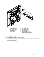
10.
Move
the
actuation
bolt
to
the
up
position
and
hand
tighten
to
hold
the
assembly
in
the
up
position.
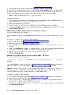
11.
At
the
front,
hold
the
MCM
module
with
one
hand
while
using
the
8mm
socket
to
unlatch
the
locking
cams.
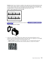
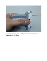
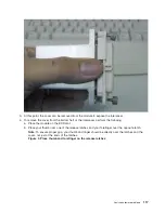
12.
With
both
hands,
grasp
the
modules
across
the
narrow
span
of
the
heatsink
cap
and
pull
the
MCM
module
from
the
system
board
and
place
it
posts
down
on
the
ESD
mat.
Figure
2.
MCM
module
(processor)
and
passsthru
modules
being
removed
Analyze
hardware
problems
107
Summary of Contents for 270
Page 2: ......
Page 12: ...x Hardware Remove and Replace Part Locations and Listings...
Page 279: ...Figure 3 CCIN 2881 with pluggable DIMM Analyze hardware problems 267...
Page 281: ...Figure 6 Models 830 SB2 with FC 9074 HSL and SPCN locations Analyze hardware problems 269...
Page 283: ...Figure 1b Model 840 SB3 processor tower dual line cord Analyze hardware problems 271...
Page 294: ...01 gif port and LED locations 282 Hardware Remove and Replace Part Locations and Listings...
Page 295: ...s src rzaq4519 gif locations Analyze hardware problems 283...
Page 483: ...Table 1 Cover assembly FC 5095 Expansion I O Tower Analyze hardware problems 471...
Page 614: ...602 Hardware Remove and Replace Part Locations and Listings...
Page 618: ...606 Hardware Remove and Replace Part Locations and Listings...
Page 621: ......
Page 622: ...Printed in USA SY44 5917 02...


