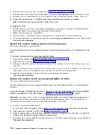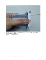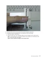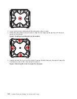
6.
Place
the
cover
side-down
on
the
ESD
mat.
Important:
Do
not
place
the
LGA
cover
face
down
on
the
ESD
mat,
because
this
may
introduce
contamination
to
the
LGA
cover
surface.
7.
At
this
point,
the
cover
can
be
removed
from
the
module
to
expose
the
interposer.
8.
Verify
that
all
four
guide
posts
are
tight.
A
loosened
guide
post
can
be
tightened
with
a
ratchet
or
wrench
until
it
is
snug.
Use
caution
not
to
damage
the
interposer.
This
ends
the
procedure.
Models
870
and
890
-
Remove
and
replace
tools:
For
use
by
authorized
service
providers.
Use
the
table
below
to
obtain
part
numbers
for
tools
needed
to
perform
remove
and
replace
procedures
on
the
Models
870
and
890.
Part
number
Units
per
assembly
Description
46H9635
1
Tool
box
11P4486
1
Torque
tool
MCM
04N6923
1
Sash
brush
11P4747
1
Magnifying
glass
11P4654
1
L3
cache
trays
11P4789
1
I/O
backplane
insertion
tool
6422789
1
DCA
removal
tool
31L8313
1
Leveling
tool
(for
rack)
47H0182
1
Torx,
T10
Analyze
hardware
problems
121
Summary of Contents for 270
Page 2: ......
Page 12: ...x Hardware Remove and Replace Part Locations and Listings...
Page 279: ...Figure 3 CCIN 2881 with pluggable DIMM Analyze hardware problems 267...
Page 281: ...Figure 6 Models 830 SB2 with FC 9074 HSL and SPCN locations Analyze hardware problems 269...
Page 283: ...Figure 1b Model 840 SB3 processor tower dual line cord Analyze hardware problems 271...
Page 294: ...01 gif port and LED locations 282 Hardware Remove and Replace Part Locations and Listings...
Page 295: ...s src rzaq4519 gif locations Analyze hardware problems 283...
Page 483: ...Table 1 Cover assembly FC 5095 Expansion I O Tower Analyze hardware problems 471...
Page 614: ...602 Hardware Remove and Replace Part Locations and Listings...
Page 618: ...606 Hardware Remove and Replace Part Locations and Listings...
Page 621: ......
Page 622: ...Printed in USA SY44 5917 02...


