


347
Part 4 Commands
As for simple interference check zone No. 1, entry into this rectangular solid area will not be
detected if Rb is outside the range of 0 to 180
. To enable detection regardless of the R-axis
coordinate, do not enter anything in coordinates 1 and 2 in the R column for zone 1.
If either the maximum value or minimum value needs not be limited, as in the case of simple
interference check zone No. 2 or 3, enter a value outside the operation area (1000 in zone 2, 1000
or -1000 in zone 3).
The maximum/minimum value may be set in either coordinate 1 or 2.
Entry into simple interference check zone No. 1, 2 or 3 will turn ON output port No. 311, 312 or 313,
respectively.
Duplicate specifications of physical output numbers or global flag numbers will cause chattering and
the result will become indeterminable. Do not set duplicate numbers.
Use of simple interference check zones will reduce the CPU performance significantly. When simple
interference check zones are not used, set “0” in "physical output port number/global flag number"
and "error type" to disable the function.
* Use a DFIF command to set a simple interference check zone in a SEL program.
(3) Notes on operation when a tool coordinate system is selected
When a tool coordinate system is selected, entry of the tool tip into the simple interference check
zone, not entry of the center of the mounting surface, will be detected.
Depending on the movement locus, a part other than the tool tip may enter the simple interference
check zone, as shown below. In this case, however, detection will not occur until the tool tip enters
the simple interference check zone. Exercise due caution.
Simple interference check zone
Tool tip
Tool tip
Simple interference check zone
348
Part 4 Commands
5. Soft Limits of SCARA Axes
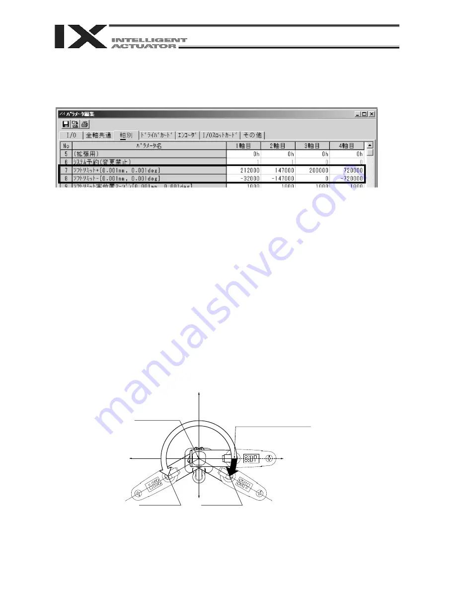
The soft limits of IX horizontal articulated robots are set in axis-specific parameter Nos. 7 and 8.
The figure below is a display example of soft limits for an IX5020 robot (arm length 500 mm, Z-axis 200
mm) in the PC software.
The soft limit parameters are set on each axis coordinate system.
Axis 1 and axis 2 correspond to arm 1 and arm 2, while axis 3 and axis 4 correspond to the Z-axis and R-
axis, respectively.
The setting unit is 0.001 deg for arm 1, arm 2 and the R-axis (rotational movement axis), while the setting
unit for the Z-axis is 0.001 mm.
The soft limits restrict the range of arm 1, arm 2, Z-axis or R-axis operation from the home of the
applicable axis coordinate system. They are not influenced by the load coordinate system or tool
coordinate system.
Note) The soft limits are set to the maximum limits of operating range when the controller is shipped.
Accordingly, do not increase the limits in the direction of expanding the operating range.
5.1 Axis Coordinate Systems and Soft Limits
(1) Soft limits of arm 1
The position where arm 1 is facing toward the +Xb direction is the home of arm 1 on its axis
coordinate system (0 degree).
It is not influenced by the position of arm 2.
The operating angle in the counterclockwise direction (positive direction) from this home defines the +
soft limit (axis 1 in axis-specific parameter No. 7). The operating angle in the clockwise direction
(negative direction) from the home defines the – soft limit (axis 1 in axis-specific parameter No. 8).
Center of rotation
of arm1
Home of arm-1 axis
coordinate system (0 degree)
Soft limit +
(212 degrees in the display
example in the PC software)
Soft limit –
(-32 degrees in the display
example in the PC software)
+Xb
-Xb
351
Summary of Contents for X-SEL PX
Page 1: ...Operation ManualSeventh Edition X SEL Controller PX QX Type Tenth Edition ...
Page 2: ......
Page 8: ......
Page 14: ......
Page 410: ...383 Appendix 386 ...
Page 452: ...425 Appendix 5 428 ...
Page 559: ......