


125
Part 3 Controller Data Structure
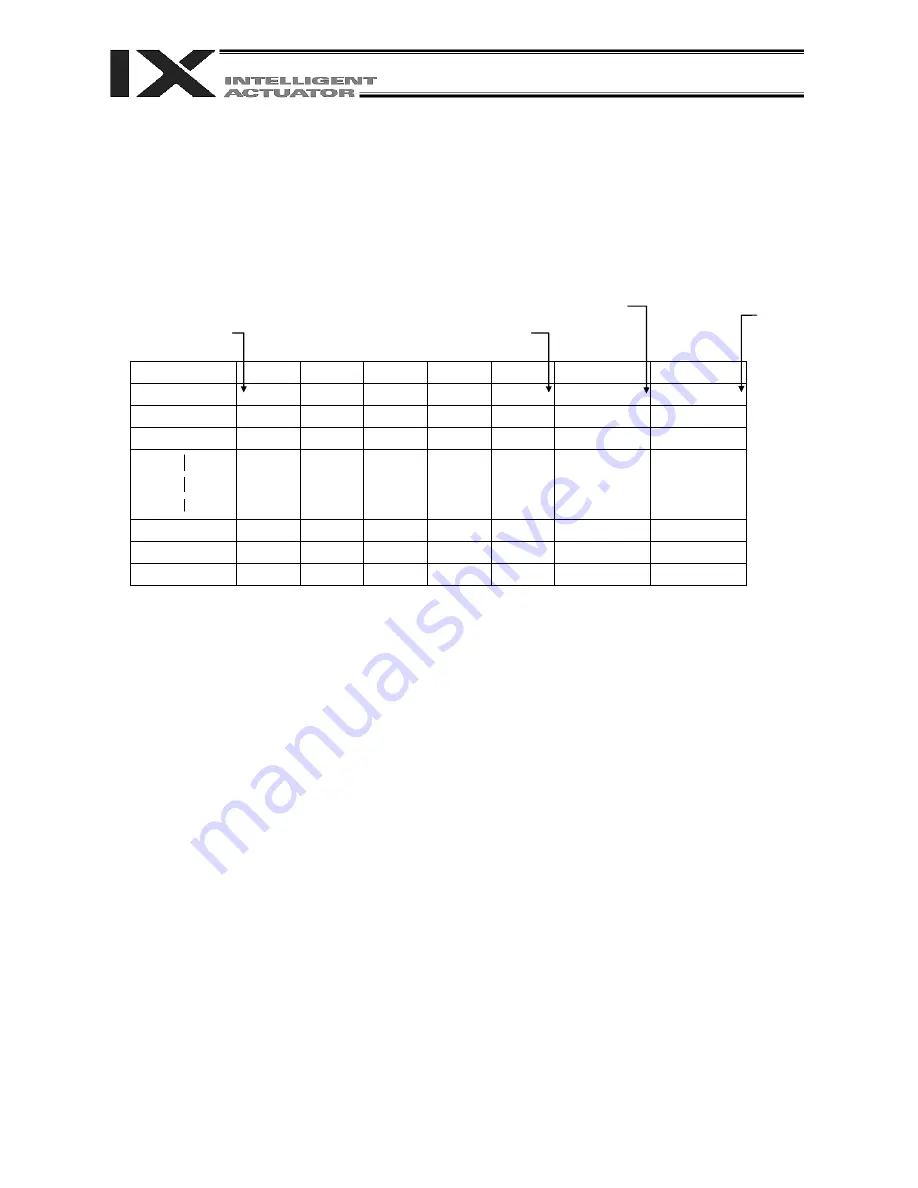
(2) Axis pattern
Whether or not each axis will be used is indicated by “1” or “0.”
(Upper) (Lower)
Axis number
Axis 6
Axis 5
Axis 4
Axis 3
Axis 2
Axis 1
Used 1 1 1 1 1 1
Not
used 0 0 0 0 0 0
[Example] When axes 1 and 2 are used
Axis 2
0011 --- The two 0s in front are not necessary. With the 0s removed, the expression reads
“11.”
Axis 1
[Example] When axes 1 and 4 are used
Axis 4
1001 --- In this case, the 0s are needed to indicate the position of axis 4.
Axis 1
Indirect specification of axis pattern in a variable
The axis pattern is considered a binary value, and the converted decimal value is assigned to a variable.
[Example] To perform home return for axis 3 only, you can specify as follows based on axis pattern:
HOME 100
In indirect specification, 100 (binary) is expressed as 4 (decimal), so the same operation can
be specified as follows:
LET
6 4
HOME *6
If you must select and specify multiple axes at the same time, use axis pattern.
Commands that use axis specification based on axis pattern
OFST, GRP, SVON, SVOF, HOME, JFWN, JFWF, JBWN, JBWF, STOP, PTST, PRED
CHVL, PBND, WZNA, WZNO, WZFA, WZFO
126
Part 3 Controller Data Structure
X-SEL language consists of a position part (position data = coordinates, etc.) and a command part
(application program).
2. Position Part
As position data, coordinates, speeds, accelerations and decelerations are set and stored.
Position No. Axis 1 Axis 2 Axis 3
Axis 4
Speed Acceleration Deceleration
1
2
3
3998
3999
4000
*1 Varies depending on the actuator model.
*2 If speed, acceleration or deceleration is set in the position data, the setting will be given priority over
the corresponding data set in the application program. Leave the position data fields empty if you
wish to enable the corresponding data in the application program.
Values pertaining to a rotating axis are processed in degrees instead of millimeters.
If axis specific parameter No. 1 (axis operation type) is set to “1” (rotational movement axis (angle control))
for a given axis, all millimeter values pertaining to that axis (including parameters, etc.) will be processed
in degrees.
If the gear ratio parameters (axis specific parameter Nos. 50 and 51) are set correctly, the angles (deg)
will represent those of the body of rotation at the end.
Example) Distance
1 mm
1 deg
Speed
1 mm
/
sec
1 deg
/
sec
Acceleration
/
deceleration 1 G = 9807 mm
/
sec
2
9807 deg
/
sec
2
99999.999 mm
*1, 2
1 ~ 2000 mm/sec
*2
Standard
0.3 G
*2
Standard
0.3 G
129
Summary of Contents for X-SEL PX
Page 1: ...Operation ManualSeventh Edition X SEL Controller PX QX Type Tenth Edition ...
Page 2: ......
Page 8: ......
Page 14: ......
Page 410: ...383 Appendix 386 ...
Page 452: ...425 Appendix 5 428 ...
Page 559: ......