IAI X-SEL PX Operation Manual Download Page 135

107

Part 3 Controller Data Structure

Chapter 1  How to Save Data 

Since the X-SEL controller uses flash memory, some data are saved by battery backup while others are 

saved in the flash memory. 

When data is transferred from the PC software or teaching pendant to the controller, the data is only 

written to the main CPU memory as shown in the diagram below and will be erased once the controller is 

powered down or reset. 

For important data, always write to the flash memory so that they will not be lost. 

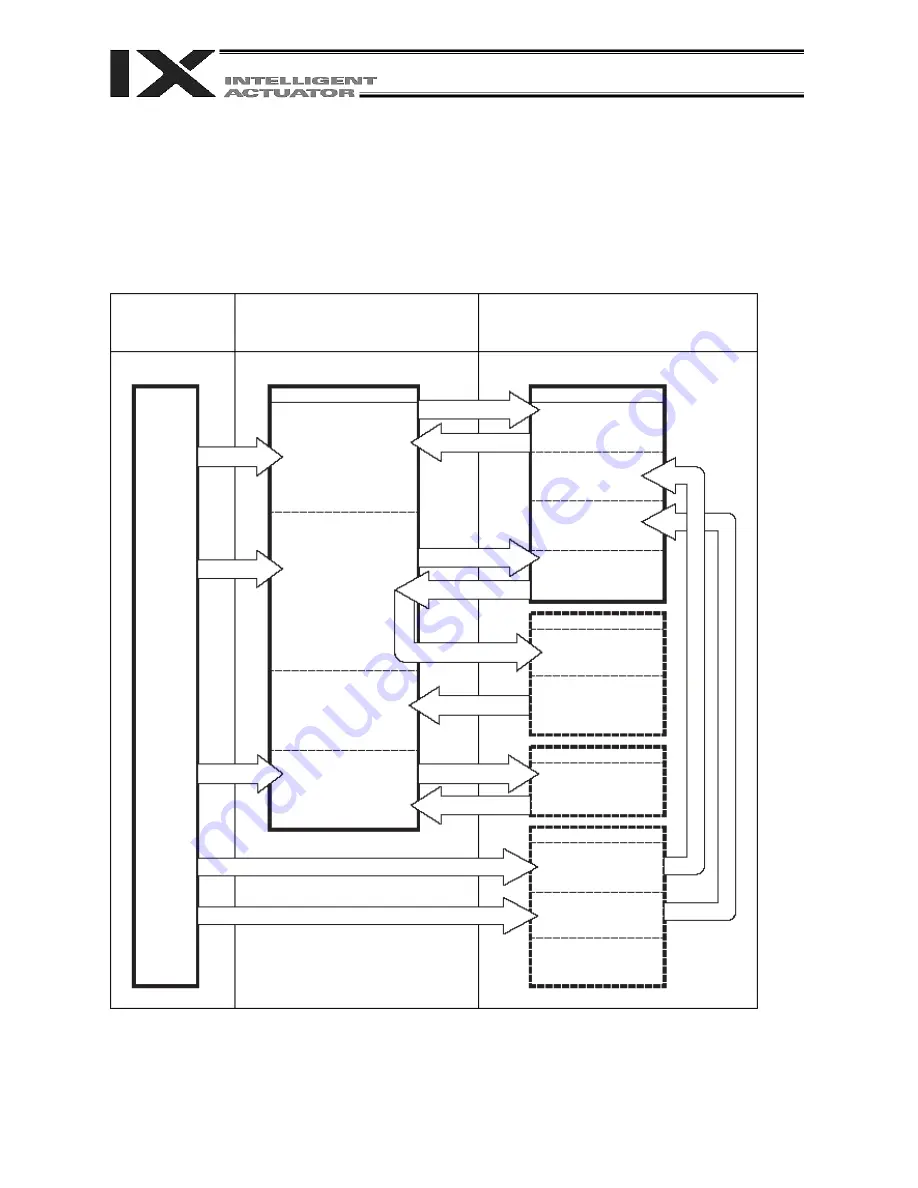
1.  Factory Settings: When the System Memory Backup Battery is Used 

1.1  Controller without Increased Memory Size 

(Other parameter No. 20 = 2 (System-memory backup battery installed)) 

Data edited on the PC 

or teaching pendant 

Data will be retained while 

the power is on and cleared 

upon reset 

Data will be retained even after the 

power is turned off 

PC

software, 

TP

Transfer

Transfer

Transfer

Main CPU memory

Programs

Parameters (other than 

slave parameters) 

Symbols

Slave card parameters 

(driver card 

parameters)

Slave card parameters 

(encoder parameters)

Write to flash memory

Write to flash memory

Transfer upon reset

Transfer upon reset

Transfer upon reset

Transfer upon reset

Transfer upon reset

Transfer

Transfer

Main CPU flash memory

Slave card memory

Slave card memory

Slave card parameters 

(driver card parameters and 

power system parameters 

that are fixed (cannot be 

changed)) 

Battery backup memory

Positions

Coordinate system 

data

SEL global data (flags, 

variables, strings) 

Error lists

Write 

to 

flash 

memory

108

Part 3 Controller Data Structure

Since the programs, parameters and symbols are read from the flash memory at restart, the data in the 

temporary memory will remain the same as the original data before edit unless the edited data are written 

to the flash memory. 

The controller always operates in accordance with the data in the main CPU memory (excluding the 

parameters). 

1.2  Controller with Increased Memory Size (with Gateway Function) 

(Other parameter No. 20 = 2 (System-memory backup battery installed)) 

The programs, parameters, symbols and positions are read from the flash memory at restart. The data in 

the main CPU memory will remain the same as the original data before edit unless the edited data are 

written to the flash memory. The controller always operates in accordance with the data in the main CPU 

memory (excluding the parameters).

Data edited on the 

PC or teaching 

pendant 

Data will be retained while the power is 

on and cleared upon reset 

Data will be retained even after the power is 

turned off 

PC

software, 

TP

Transfer

Transfer

Transfer

Main CPU RAM memory

Programs

Parameters (other than 

slave parameters) 

Symbols 

Positions (X-SEL axis)

(No.10001~20000)

Slave card 

parameters  

(Variable driver 

parameters)

Slave card parameters

(Encoder parameters, 

etc.)

Write to flash memory

Write to flash memory

Transfer upon reset

Transfer upon reset

Transfer upon reset

Transfer upon reset

Transfer upon reset

Transfer

Transfer

Main CPU flash memory

Slave card memory

Slave card memory

Battery backup memory

SEL global data (flags, 

variables, strings) 

Error lists

Write 

to 

flash 

memory

Transfer

Write 

to 

flash 

memory

Slave card parameters 

(Fixed driver parameters 

and power-supply 

parameters) 

(Cannot be changed)

Positions (X-SEL axis) 

(Nos. 1 to 10000) 

Coordinate system data 

User-data backup 

memory 

(Positions (RC axis))

111

Summary of Contents for X-SEL PX

Page 1: ...Operation ManualSeventh Edition X SEL Controller PX QX Type Tenth Edition ...

Page 2: ......

Page 3: ...ading the Operation Manual keep it in a convenient place so that whoever is handling this product can reference it quickly when necessary Important This Operation Manual is original The product cannot be operated in any way unless expressly specified in this Operation Manual IAI shall assume no responsibility for the outcome of any operation not specified herein Information contained in this Opera...

Page 4: ...pproximately 3 2 V Data backup becomes impossible at a battery voltage of approximately 2 7 V rated voltage 3 6 V To prevent this problem the controller can output a low battery voltage alarm from its I O port Output port No 313 is assigned as an alarm output for low system memory backup battery voltage Output port No 314 is assigned as an alarm output for low absolute encoder backup battery volta...

Page 5: ...capacity 45 W Arm length 500 to 800 23 W Arm length 250 to 350 14 W Arm length 120 to 150 Note When the arm length is 120 to 180 the brake power need not be supplied to the robot SCARA robot Notes on Supply of Brake Power 24 V Besides connecting the brake power cable from the SCARA robot the brake power must also be supplied to the controller Follow the illustration below to supply the brake power...

Page 6: ...may generate a drive source cutoff relay error E6D notifying fusion of an internal relay when the time after the power is turned off until it is turned back on until the power is reconnected is too short Although the specific time varies depending on the input voltage and number of external regenerative resistance boxes being connected as a guide wait for at least 40 seconds before reconnecting th...

Page 7: ... later How to Check if Controller Has Increased Memory Size Check the ROM version information in the PC software Version 6 0 0 0 or later by selecting Controller C About ROM V or check the main CPU firmware version information on the teaching pendant IA T X IA T XD Version 1 121 or later SEL T SEL TD Version 1 00 or later by selecting Moni Ver Main If the memory size has been increased On the PC s...

Page 8: ......

Page 9: ...31 2 3 Current Monitor and Variable Monitor 32 Chapter 5 Specifications 34 1 Controller Specifications 34 2 External I O Specifications 38 2 1 NPN Specification 38 2 2 PNP Specification 40 3 Power Source Capacity and Heat Output 42 4 External Dimensions 48 Chapter 6 Safety Circuit 57 1 Items to Notes 57 2 Safety Circuit for PX Type Standard Specification Controller 58 3 Safety Circuit for QX Type ...

Page 10: ...uest 105 Part 3 Controller Data Structure 109 Chapter 1 How to Save Data 110 1 Factory Settings When the System Memory Backup Battery is Used 110 1 1 Controller without Increased Memory Size 110 1 2 Controller with Increased Memory Size with Gateway Function 111 2 When the System Memory Backup Battery is Not Used 112 2 1 Controller without Increased Memory Size 112 2 2 Controller with Increased Me...

Page 11: ...izing Related 296 1 21 Palletizing Calculation Command 311 1 22 Palletizing Movement Command 314 1 23 Building of Pseudo Ladder Task 320 1 24 Extended Commands 322 Chapter 3 Key Characteristics of Horizontal Articulated Robot SCARA Operation 327 1 CP Operation and PTP Operation 327 2 Arm System 330 3 SCARA Coordinate System 338 4 Simple Interference Check Zone Dedicated SCARA Function 348 5 Soft L...

Page 12: ...during Path Movement 393 8 Circular Arc Operation 394 9 Output of Home Return Complete Signal for Linear Axes 395 10 Axis Movement by Input Waiting and Output of Complete Signal 396 11 Change of Moving Speed for Linear Axes 397 12 Speed Change during Operation 398 13 Local Global Variables and Flags 399 14 How to Use Subroutines 400 15 Pausing of Operation 401 16 Aborting of Operation 1 CANC 402 1...

Page 13: ...447 3 Axis Specific Parameters 451 4 Driver Card Parameters 462 5 Encoder Parameters 465 6 I O Device Parameters 466 7 Other Parameters 467 8 Manual Operation Types 473 9 Use Examples of Key Parameters 474 Combination Table of X SEL PX QX Axis 5 6 Linear Rotary Control Parameter Other than SCARA Axes 480 Error Level Control 481 Error List 524 Troubleshooting of X SEL Controller 528 Servo Gain Adju...

Page 14: ......

Page 15: ...stablished in a hierarchical manner under the International Standards ISO IEC The safety standards that apply to industrial robots are as follows Type C standards individual safety standards ISO10218 Manipulating industrial robots Safety JIS B 8433 Manipulating industrial robots Safety Also Japanese laws regulate the safety of industrial robots as follows Industrial Safety and Health Law Article 5...

Page 16: ...operation Article 150 3 Sign etc indicating that work is in progress Article 150 3 Provision of special education Article 36 31 During teaching etc Not cut off Checkup etc before commencement of work Article 151 To be performed after stopping the operation Article 150 5 Cut off Sign etc indicating that work is in progress Article 150 5 Preparation of work rules Article 150 5 Measures to enable imm...

Page 17: ...lti joint robot whose movable radius and Z axis are within 300 mm Among the products featured in our catalogs the following models are classified as industrial robots 1 Single axis ROBO Cylinders RCS2 RCS2CR SS8 whose stroke exceeds 300 mm 2 Single axis robots The following models whose stroke exceeds 300 mm and whose motor capacity also exceeds 80 W ISA ISPA ISDA ISPDA ISWA ISPWA IF FS NS 3 Linea...

Page 18: ...o bump or drop the product Use appropriate means for transportation Do not step on the package Do not place on the package any heavy article that may deform the package When using a crane of 1 ton or more in capacity make sure the crane operators are qualified to operate cranes and perform slinging work When using a crane etc never hoist articles exceeding the rated load of the crane etc Use hoist...

Page 19: ...asures so that the product cannot be started only by turning on the power If the product starts suddenly injury or product damage may result Implement safety measures so that the product will not start upon cancellation of an emergency stop or recovery of power following a power outage Failure to do so may result in injury equipment damage etc Put up a sign saying WORK IN PROGRESS DO NOT TURN ON P...

Page 20: ...ct damage 8 Maintenance inspection Whenever possible work from outside the safety fences If work must be performed inside the safety fences prepare work rules and make sure the operator understands the procedures thoroughly When working inside the safety fences turn off the power switch as a rule When working inside the safety fences the operator should carry a handy emergency stop switch so that ...

Page 21: ...ve the instruction will result in an imminent danger leading to death or serious injury Danger Warning Failure to observe the instruction may result in death or serious injury Warning Caution Failure to observe the instruction may result in injury or property damage Caution Note The user should take heed of this information to ensure the proper use of the product although failure to do so will not...

Page 22: ...CE Marking If a compliance with the CE Marking is required please follow Overseas Standards Compliance Manual ME0287 that is provided separately Pre 8 ...

Page 23: ... poor contact or even a runaway system This section explains prohibited handling of cables Read the information carefully to connect the cables properly Ten Rules for Handling Cables Must be Observed 1 Do not let the cable flex at a single point 2 Do not let the cable bend kink or twist 3 Do not pull the cable with a strong force 4 Do not let the cable receive a turning force at a single point 6 D...

Page 24: ...ucture of cable will vary depending on the manufacturer and type of cable Need for Robot Cables A cable connected to a moving part of an actuator system will inevitably receive repeated bending loads at the base of the cable As a result the cores in the cable may break over time To minimize the risk of cable breakage we strongly recommend that a robot cable offering significantly higher flexibilit...

Page 25: ...us type ET Ethernet type I O board I O board I O board I O board I O board I O board I O board I O board I O board I O board I O board I O board Standard specification Introduction Thank you for purchasing the X SEL controller Inappropriate use will prevent this product from operating at its full potential and may even cause unexpected failure or result in a shortened service life Please read this...

Page 26: ...type Not used Not used Not used Not used I O board I O board I O board I O board I O board I O board I O board I O board I O board I O board I O board I O board I O board I O board I O board I O board I O board I O board I O board I O board I O board I O board I O board I O board Standard specification 3 phase 1 2 3 4 5 6 7 8 9 10 None Single phase Type Conventional models RCS2 RA7 LSA series mode...

Page 27: ...I recommends that our cartesian axis actuators be used at a duty of 50 or less as a guideline in view of the relationship of service life and accuracy The duty is calculated by the formula specified below Duty Inactivity time Motion Time on Decelerati on Accelerati X 100 After turning off the control power be sure to wait for at least 5 seconds or 40 seconds in the case of a P type controller of s...

Page 28: ...ve any question regarding the content of this manual please contact IAI 2 Always use the specified genuine IAI cables for wiring between the controller and the actuator 3 Do not enter the operation area of the machine while the machine is operating or ready to operate the controller power is on If the machine is used in a place accessible to other people provide an appropriate safety measure such ...

Page 29: ...ion Defect caused by inappropriate handling or use by the user Defect caused by inappropriate or erroneous maintenance inspection Defect caused by use of a part other than IAI s genuine part Defect caused by unauthorized modification etc not approved by IAI or its agent Defect due to an act of God accident fire etc Only the product itself without accessories cables etc is covered by the warranty T...

Page 30: ...ounding Air Temperature Range 0 40 C Surrounding Humidity Range 10 95 non condensing conforming to JIS C3502 RH 2 Storage Temperature Range 25 C 70 C excluding the battery Maximum Operating Altitude 2000 m Protection Class IP20 Vibration 10 f 57 0 035 mm continuous 0 075 mm intermittent 57 f 150 4 9 m s2 continuous 9 8 m s2 intermittent X Y and Z directions Impact 147 mm s2 11 ms half sine pulse 3...

Page 31: ...mm below the controller If multiple controllers are to be installed side by side providing additional fans on top of the controllers will help maintain a uniform surrounding air temperature Provide a minimum clearance of 150 mm between the front side of the controller and a wall enclosure If multiple controllers are to be connected on top of one another prevent the controller above from taking in ...

Page 32: ...ree times the rated current and select breakers and other components based on a power supply capacity of 1 5 times the rated power supply capacity 2 Leak current When installing the controller always provide an inverter type earth leakage breaker The table below lists the controller leak currents excluding the currents leaked from the servo system Model Leak current control power supply Leak curre...

Page 33: ...ent of circuit breaker Rated motor power supply capacity VA Control power supply capacity VA AC input voltage x Safety factor rough guide 1 2 to 1 4 2 Earth leakage breaker Install an earth leakage breaker on the AC power supply line side primary side of the controller to cut off earth leakage current One earth leakage breaker may be used to serve both the motor power and plant power You must sele...

Page 34: ...ring core and clamp filters to ensure compliance with the EC Directives IAI uses the following filters in the evaluation certification tests under the EMC Directives Recommended Noise Filter Ring Core and Clamp Filters Supplier Model Noise filter Densei Lambda MC1320 for three phase power supply MXB 1220 33 for single phase power supply Ring core NEC Tokin ESD R 25 Clamp filter A TDK ZCAT3035 1330...

Page 35: ...le Motor cable Actuator Controller System I Os Brake 24 VDC power supply Emergency stop switch Encoder cable Motor cable Actuator Electro magnetic contactor Safety relay Safety circuit Control panel Circuit breaker Earth leakage breaker Single phase noise filter Ring core Clamp filters Controller System I Os Brake 24 VDC power supply Emergency stop switch 200 VAC 3 phase power supply bus Surge pro...

Page 36: ...troller System I Os Brake 24 VDC power supply Emergency stop switch Encoder cable Actuator Electro magnetic contactor Safety relay Safety circuit Control panel Circuit breaker Earth leakage breaker Ring core Clamp filters Controller System I Os Brake 24 VDC power supply Emergency stop switch Motor cable 200 VAC single phase power supply bus Three phase noise filter 200 VAC single phase power suppl...

Page 37: ... power cable Wire the controller cables separately from lines creating a strong electric field such as power circuit lines by not bundling them together or placing in the same cable duct If you wish to extend the motor cable or encoder cable beyond the length of each supplied cable please contact IAI s Technical Service Section or Sales Engineering Section 2 Noise elimination grounding Provide ded...

Page 38: ...a diode in parallel with the coil Determine the diode capacity in accordance with the load capacity In a DC circuit connecting a diode in reversed polarity will damage the diode internal parts of the controller and DC power supply Exercise due caution The above noise elimination measures are particularly important when a 24 VDC relay is driven directly by a controller output and there is also a 10...

Page 39: ...15 Part 1 Installation Reference Circuit Diagram Surge absorber Solenoid valve Controller 0 V 15 ...

Page 40: ...n Chapter 4 Name and Function of Each Part 1 Front View of Controller PX Type Standard Specification 4 axes SCARA axes only PX Type Standard Specification expanded by 2 additional linear movement axes with I O brake unit 16 ...

Page 41: ...17 Part 1 Installation QX Type Global Specification 4 axes SCARA axes only QX Type Global Specification expanded by 2 additional linear movement axes with I O brake unit 17 ...

Page 42: ...wer system overhear error will generate In this case connect a regenerative unit or units Whether or not your system needs one or more regenerative units depends on the specific application such as the configuration of linear movement axes Refer to Appendix Number of Regenerative Units to be Connected If all axes are SCARA axes no regenerative unit is required External Regenerative Unit Connector ...

Page 43: ...l 2 IN MP_L Motor power 200 VAC phase L Single phase specification Terminal assignments 1 IN MP_N Motor power 200 VAC phase N Cable size 2 mm2 AWG14 6 PE Protective grounding wire 5 IN CP_L Control power 200 VAC phase L 4 IN CP_N Control power 200 VAC phase N Cable size 0 75 mm2 AWG18 3 IN MP_R Motor power 200 VAC phase R 2 IN MP_S Motor power 200 VAC phase S Three phase specification Terminal ass...

Page 44: ...G1 6 Encoder axis sensor connector Maximum wiring distance 30 m Pin No Signal name Description Signal table 1 2 3 4 5 6 7 SRD Send receive differential pulse magnetic pole switching 8 SRD Send receive differential pulse magnetic pole switching 9 NC Not connected 10 NC Not connected 11 NC Not connected 12 24VOUT Sensor power output 13 0V 24 V power ground 14 BATT Backup battery 15 BATTGND Battery g...

Page 45: ... phase W The position of the motor connector for each axis varies depending on the SCARA type as shown below 8 Teaching pendant type switch P type only This switch is used to change the type of the teaching pendant connected to the teaching connector 9 It switches between IAI s standard teaching pedant and ANSI teaching pendant The switch is located on the front side of the board Select the applic...

Page 46: ...ndefined lines etc Baud rate Up to 115 2 kbps Half duplex communication speeds of up to 115 2 kbps are supported Maximum wiring distance 10M At 38 4 kbps Interface standard RS232C Connected unit Dedicated teaching pendant IAI s standard teaching pendant for X SEL or ANSI teaching pendant Connection cable Dedicated cable Power supply 5 VDC or 24 VDC A multi fuse MF R090 is installed to protect each...

Page 47: ...1 NC Not connected 12 Out EMGOUT1 Emergency stop contact 1 13 In EMGIN1 14 NC Not connected 15 Out RSVVCC 24 V power supply for IA T XA SEL T D teaching pendant 16 Out EMGOUT2 Emergency stop contact 2 17 Out ENBVCC1 Enable drive power 1 18 Out VCC Power output Power supply for IA T X D teaching pendant 19 In ENBTBX1 Enable input 1 20 In DTR Terminal ready 21 Out ENBVCC2 Enable drive power 2 22 In ...

Page 48: ...rminal Assignments Pin No Signal name Description 9 DET IN External contact error input 8 IN Emergency stop detection input 7 EMGin 24V 24 V power output for emergency stop detection input 6 line 5 EMG1 line Emergency stop switch 1 8 mA PX type 4 line 3 EMG2 line Emergency stop switch 2 8 mA PX type 2 Out Left 1 SDN Out External relay drive cutoff contact output 18 DET 24V 24 V power output for ex...

Page 49: ...peration mode To operate the switch pull it toward you and tilt Tilting the switch upward will select MANU manual mode while tilting it downward will select AUTO auto mode Teaching can be performed only in the MANU mode but auto program start is not enabled in the MANU mode If you are using a QX type controller connect the supplied dummy plug to the teaching connector 9 during the AUTO mode 13 Sta...

Page 50: ...al purpose input White 2 20 018 General purpose input Black 2 21 019 General purpose input Brown 3 22 020 General purpose input Red 3 23 021 General purpose input Orange 3 24 022 General purpose input Yellow 3 25 023 General purpose input Green 3 26 024 General purpose input Blue 3 27 025 General purpose input Purple 3 28 026 General purpose input Gray 3 29 027 General purpose input White 3 30 028...

Page 51: ...c Half duplex communication Connection cable PC AT standard 232C cross cable 1 In CD Carrier detection Not used Terminal assignments 2 In RD Received data RXD 3 Out SD Transmitted data TXD 4 Out ER Equipment ready DTR 5 In SG Signal ground 6 In DR Data set ready DSR 7 Out RS Request to send RTS Not used 8 In CS Clear to send CTS Not used 9 NC Not used Use a cross cable to connect to the RS232C por...

Page 52: ...nnector Specifications Item Overview Details Connector Phoenix Contact MC1 5 2 G 3 5 Cable end connector Phoenix Contact MC1 5 2 ST 3 5 Applicable cable size 0 1 2 0 mm2 AWG28 14 Connector name BK PWR Input voltage 24 VDC 10 0 V 24 V power ground Terminal assignments 24 V 24 V power input 21 Brake release switch connector Linear movement axis only This connector accepts a switch that releases the ...

Page 53: ...lt Tilting the switch upward RLS side will release the brake forcibly while tilting it downward NOM will enable the controller to release the brake Note The SCARA axis brake switch is located on the panel of the SCARA robot 23 Conveyor tracking connector This connector is used only when the controller is of conveyor tracking specification Normally this connector is not used 29 ...

Page 54: ...nput except during the update mode 6 Operation is paused and waiting for a restart signal except during the update mode 7 All servo axes are interlocked except during the update mode 8 Message level error 8 Message level error 9 Core update mode 9 Core update is in progress 9 Core update has completed 9 Slave update mode 9 Slave update is in progress 9 Slave update has completed 9 A program is run...

Page 55: ...ioncancellation level error 2 Message level error 2 Message level error 2 Application update mode 2 Application update is in progress 2 Application update has completed 2 Hardware test mode process 2 Clearing the application flash ROM 2 Application flash ROM has been cleared 2 Jump to the application 2 Core flash ROM check process 2 Application flash ROM check process 2 SDRAM check process 1 The p...

Page 56: ...will show the current for axis 3 Axis 6 Axis 5 Axis 4 Axis 3 When data is written to the flash ROM or a software reset restart is executed after the parameter values have been input the panel window will show the motor current to rating ratio by a segment pattern instead of ready status or program run number The segment display patterns and corresponding motor current to rating ratios are shown be...

Page 57: ...ameter No 49 2 Other parameter No 50 Variable number of the global integer variable to be monitored When data is written to the flash ROM or a software reset restart is executed after the parameter values have been input the panel window will show the content of the global integer variable instead of ready status or program run number The far left segment digit should read U Display example 33 ...

Page 58: ...nable input Contact B input Internal power supply type System ready output No voltage contact relay output for generation of equipment ready signal based on the wired OR logic among multiple equipment Max 500 mA 24 VDC Axis control method AC full digital servo Position detection methods 17 bit incremental encoder Wire saving type 17 bit rotation data backup absolute encoder Resolution 14 bits unde...

Page 59: ... or ANSI teaching pendant selected by a switch RS232C port for general PC connection Dedicated 2 channel RS232C 9 pin DTE specification Half duplex at speeds up to 115 2 kbps 1 channel or up to 76 8 kbps simultaneous communication with 2 channels Note 3 Expanded inputs outputs optional Expandable to 3 slots Fieldbus interface optional Profibus DP IN 32 bytes max OUT 32 bytes max DeviceNet IN 32 by...

Page 60: ...tion of equipment ready signal based on the wired OR logic among multiple equipment Max 500 mA 24 VDC Axis control method AC full digital servo Position detection methods 17 bit incremental encoder Wire saving type 17 bit rotation data backup absolute encoder Resolution 14 bits under both methods 16384 pulses Batteries Absolute data backup battery AB 5 made by IAI System memory backup battery CR20...

Page 61: ...h the controller and actuator connected make sure the test voltage and duration will not exceed 1000 V and 1 minute respectively Note 2 If one RS232C channel is used at a communication speed of 115 2 kbps use the other channel at 38 4 kbps or below If these speeds are exceeded an overrun error or other problems will occur and successful communication cannot be guaranteed RCS2 R 7 LS and LSA series...

Page 62: ...collector type 4 Sequencer contact output minimum load of approximately 5 VDC 1 mA Input circuit P24 I O interface pin No 1 Caution If a non contact circuit is connected externally malfunction may result from leakage current Use a circuit in which leakage current in a switch off state does not exceed 1 mA X SEL controller s input signal At the default settings the system recognizes the ON OFF dura...

Page 63: ...the maximum total load current of every eight ports from output port No 300 the maximum total load current of output port No 300 n to No 300 n 7 is 400 mA where n is 0 or a multiple of 8 Output circuit P24 I O interface pin No 1 N I O interface pin No 50 Caution In the event that the load is short circuited the overcurrent protection circuit will cut the power However give due consideration to the...

Page 64: ...ector type 4 Sequencer contact output minimum load of approx 5 VDC 1 mA Input circuit N I O interface pin No 50 Caution If a non contact circuit is connected externally malfunction may result from leakage current Use a circuit in which leakage current does not exceed 1 mA X SEL controller s input signal At the default settings the system recognizes the ON OFF durations of input signals if they are...

Page 65: ...m total load current of every eight ports from output port No 300 the maximum total load current of output port No 300 n to No 300 n 7 is 400 mA where n is 0 or a multiple of 8 Output circuit P24 I O interface pin No 1 N I O interface pin No 50 Caution In the event that the load is short circuited the overcurrent protection circuit will cut the power However give due consideration to the circuit c...

Page 66: ...ists of the standard units connected to every controller and optional units such as an I O card Therefore the power consumption and heat output of the control part will vary depending on the system configuration Additionally heat outputs from the units operated by an external power source must also be considered The table below lists the power consumption of various controller units List of Power ...

Page 67: ...y coefficient and power factor to the sum of all power consumptions of controlled units based on the applicable values shown in the table 2 Heat output of the control system The heat output of the controller s control system is obtained as the total sum of all internal power consumptions of controlled units and internal power consumptions of external power sources based on the applicable values sh...

Page 68: ...elow lists per axis motor power consumptions List of Motor Drive Powers Power W rated output Power 0 6 Power factor VA Output stage loss W NN 1205 NN 1505 NN 1805 129 8 216 3 8 13 NN 2515H NN 3515H TNN 3015H TNN3515H UNN3015H UNN3515H 1117 9 1863 1 44 8 NN 50 H NN 60 H HNN5020H HNN6020H INN5020H INN6020H 2218 0 3696 7 69 7 NN 70 H NN 80 H HNN7020H HNN8020H INN7020H INN8020H 3880 6 6467 7 93 2 SCAR...

Page 69: ...1163 7 27 20 Linear movement axis 750W 912 8 1521 3 29 77 The power values in the table include the motor drive power copper loss and driver output loss 1 Motor power source capacity The power source capacity of the motor power supply is obtained as the total sum of all powers for the number of actuators used based on the applicable values shown in the table 2 Heat output of the motor power supply...

Page 70: ...9 2 63 3 1 6 2 4 5 2 5 1 6 1 1 0 72 2 5 3 56 9 W 3 I O power source capacity 24 VDC 6 1 1 6 1 W 4 Brake power source capacity 24 VDC 2 5 5 8 3 24 9 W 5 Motor power source capacity SCARA 1 871 3 VA Linear movement axis 421 0 233 5 654 5 VA 1871 3 654 5 2525 8 VA 6 Heat output from motor power supply 44 12 9 12 6 12 59 4 W 7 Power source capacity 1 Control power source capacity 5 Motor power source ...

Page 71: ...m length 250 to 350 mm NN 2515 3515H NN3015 3515H 1987 1 78 5 Arm length 500 to 600 mm NN 5020H 5030H 6020H 6030H NN5020H 5030H 6020H 6030H 3820 7 97 9 Arm length 700 to 800 mm NN 7020H 7030H 8020H 8030H NN7020H 7030H 8020H 8030H 6591 7 134 8 High speed models High speed type NSN5016H 6016H 6962 1 128 6 Arm length 250 to 350 mm NN 2515 3515H NN3015 3515H 1150 3 69 7 Arm length 500 to 600 mm NN 502...

Page 72: ... 60 HNN5020 HNN6020 INN5020 INN6020 Arm length 250 to 600 mm NN 70 NN 80 HNN7020 HNN8020 INN7020 INN8020 Arm length 700 800 mm NSN5016 NSN6016 High speed type PX type QX type PX type QX type PX type QX type PX type QX type Without expansion I O board 4 1 4 9 4 5 4 13 4 7 4 15 4 7 4 15 SCARA axes only With expansion I O board 4 2 4 10 4 6 4 14 4 8 4 16 4 8 4 16 1 4 3 4 11 Without expansion I O boar...

Page 73: ...ple of applicable model X SEL PX NNN1205 N1 N1N1N1 2 3 49 5 49 5 75 75 3 5 80 3 125 3 5 249 265 3 5 41 120 120 41 195 186 180 195 186 180 5 322 338 4 2 PX QX Type Three phase Standard Specification Single phase Global Specification Single phase Standard Specification Controller Fig 4 1 PX QX Type Three phase Standard Specification Single phase Global Specification Single phase Standard Specificati...

Page 74: ...180 mm without expansion I O board with incremental linear movement axis without brake Fig 4 4 PX QX Type Three phase Standard Specification Single phase Global Specification Single phase Standard Specification 5 6 axis specification SCARA arm length 120 150 180 mm with expansion I O board with incremental linear movement axis without brake Example of applicable model X SEL PX NNN1205 200I 200I N1...

Page 75: ...d Specification 4 axis specification SCARA arm length 250 to 600 mm without expansion I O board Fig 4 6 PX QX Type Three phase Standard Specification Single phase Global Specification Single phase Standard Specification 4 axis specification SCARA arm length 250 to 600 mm with expansion I O board Example of applicable model X SEL PX NNN2515 N1 EEE 2 3 Example of applicable model X SEL PX NNN2515 N1...

Page 76: ... of the motor connector encoder axis sensor connector varies depending on the SCARA model Fig 4 8 PX QX Type Three phase Standard Specification Single phase Global Specification Single phase Standard Specification 5 6 axis specification SCARA arm length 250 to 600 mm with expansion I O board 5 6 axis specification SCARA arm length 120 150 180 mm with expansion I O board with absolute linear moveme...

Page 77: ...ample of applicable model X SEL QX NNN1205 N1 EEE 2 3 Example of applicable model X SEL QX NNN1205 N1 N1N1N1 2 3 Fig 4 9 QX Type Three phase Global Specification 4 axis specification SCARA arm length 120 150 180 mm without expansion I O board Fig 4 10 QX Type Three phase Global Specification 4 axis specification SCARA arm length 120 150 180 mm with expansion I O board 53 ...

Page 78: ... QX NNN1205 200I 200I N1 N1N1N1 2 3 Fig 4 11 QX Type Three phase Global Specification 5 6 axis specification SCARA arm length 120 150 180 mm without expansion I O board with incremental linear movement axis without brake Fig 4 12 QX Type Three phase Global Specification 5 6 axis specification SCARA arm length 120 150 180 mm with expansion I O board with incremental linear movement axis without bra...

Page 79: ...N2521 N1 EEE 2 3 Example of applicable model X SEL QX NNN2515 200I 200I N1 N1N1N1 2 3 Fig 4 13 QX Type Three phase Global Specification 4 axis specification SCARA arm length 250 to 600 mm without expansion I O board Fig 4 14 QX Type Three phase Global Specification 4 axis specification SCARA arm length 250 to 600 mm with expansion I O board 55 ...

Page 80: ...is with brake SCARA arm length 700 800 mm without expansion I O board High speed type without expansion I O board Availability and position of the motor connector encoder axis sensor connector varies depending on the SCARA model Fig 4 16 QX Type Three phase Global Specification 5 6 axis specification SCARA arm length 250 to 600 mm with expansion I O board 5 6 axis specification SCARA arm length 12...

Page 81: ...ic reset using the emergency stop switch or a method requiring both an emergency stop switch action and an external input signal can be selected by a parameter I O parameter No 44 During an emergency stop the status can be output to an external device set by I O parameter No 48 2 Overview of enabling action Enabling operation via the safety gate or the deadman switch on the teaching pendant implem...

Page 82: ...cuit cannot be driven by an external power source Do not use the internal power supply provided for the system I O connector for any other purpose It may damage the equipment or cause it to malfunction The tables below list the signals and wiring methods of the safety circuit interface connector System I O Connector for PX Type Item Overview Details COMBICON 2 row 9 pin MCD1 5 9 G1 3 5P26THR by Ph...

Page 83: ...tly as incorrect wiring will compromise the safety mechanisms of the controller The RDYOUT contacts will close only when the controller has started properly By connecting these contacts in series with similar contacts of other equipment the soundness of the entire system can be checked easily PX type X SEL controller External emergency stop circuit Emergency stop switch Enable switch 59 ...

Page 84: ... note that IAI is not liable for any losses arising from a malfunction of the safety circuit configured by the user The ANSI safety standard can be met only when an ANSI teaching pendant is connected to the teaching port The redundant emergency stop lines and enabling lines are designed with the assumption that they will be driven by a power source external to the controller Note however that the ...

Page 85: ...must be connected to meet safety category 3 or above They are designed to provide redundant safety circuits In the table the signal shown in fields DET provides an input for detecting malfunction of the safety circuit mainly fused relay contacts This signal is disabled when the controller is shipped To enable the DET input set bits 8 to 11 of I O parameter No 24 to 1 change I O parameter No 24 fro...

Page 86: ...otify the controller of the drive source cutoff input received by the drive source cutoff circuit via an EMG signal ENBin IN and ENBin 24V are contact inputs that notify the controller via an ENB signal These contact signals are used to decelerate the actuator to a stop or turn off the servo Normally a safety relay output is connected to each of these inputs RDY RDY OUT and RDY OUT are output cont...

Page 87: ...power stage External emergency stop reset contact output Teaching pendant Power on reset MPSDWN bit Power error Mushroom emergency stop switch EMG SW contact 1 EMG SW contact 2 Double position enabling control switch DEADMAN SW contact 1 DEADMAN SW contact 2 Emergency stop status Enable status Digital control part 63 ...

Page 88: ...or NEO SC Relay Contactor NEO SC 200 VAC three phase Reset switch External emergency stop switch External EMG switch contact 1 External EMG switch contact 2 Safety relay unit G9SA 301 by Omron Safety gate switch External SGATE contact 1 External SGATE contact 2 64 ...

Page 89: ...to 3 0 The RDYOUT output system I O is SYSRDY PIO trigger program operation enabled and the hardware is normal emergency stop is not actuated and no hardware errors are detected I O parameter No 44 0 The drive source cutoff reset input is not yet used I O parameter No 47 3 Output function 301 READY output PIO program operation enabled and no errors of cold start level or higher have occurred 200 V...

Page 90: ...meter No 47 3 Output function 301 READY output PIO program operation enabled and no errors of cold start level or higher have occurred 200 VAC control power Normal CPU start I O output signal Port No 301 Ready output Rdy system I O SDN system I O EMG1 EMG2 system I O ENB1 ENB2 system I O Occurrence of secret level error Occurrence of message level error Occurrence of operation cancellation level e...

Page 91: ...0 The drive source cutoff reset input is not yet used I O parameter No 47 3 Output function 301 READY output PIO program operation enabled and no errors of cold start level or higher have occurred 200 VAC control power Normal CPU start I O output signal Port No 301 Ready output Rdy system I O SDN system I O EMG1 EMG2 system I O ENB1 ENB2 system I O Occurrence of secret level error Occurrence of me...

Page 92: ... I O parameter No 47 3 Output function 301 READY output PIO program operation enabled and no errors of cold start level or higher have occurred 200 VAC control power Normal CPU start I O output signal Port No 301 Ready output Rdy system I O SDN system I O EMG1 EMG2 system I O ENB1 ENB2 system I O Occurrence of secret level error Occurrence of message level error Occurrence of operation cancellatio...

Page 93: ...put is not yet used I O parameter No 47 3 Output function 301 READY output PIO program operation enabled and no errors of cold start level or higher have occurred 200 VAC control power Normal CPU start I O output signal Port No 301 Ready output Rdy system I O SDN system I O EMG1 EMG2 system I O ENB1 ENB2 system I O Occurrence of secret level error Occurrence of message level error Occurrence of op...

Page 94: ...unction 301 READY output PIO program operation enabled and no errors of cold start level or higher have occurred 200 VAC control power Normal CPU start I O output signal Port No 301 Ready output Rdy system I O SDN system I O EMG1 EMG2 system I O ENB1 ENB2 system I O Occurrence of secret level error Occurrence of message level error Occurrence of operation cancellation level error Occurrence of col...

Page 95: ...47 3 Output function 301 READY output PIO program operation enabled and no errors of cold start level or higher have occurred 200 VAC control power Normal CPU start I O output signal Port No 301 Ready output Rdy system I O SDN system I O EMG1 EMG2 system I O ENB1 ENB2 system I O Occurrence of secret level error Occurrence of message level error Occurrence of operation cancellation level error Occu...

Page 96: ... hardware errors are detected I O parameter No 44 0 The drive source cutoff reset input is not yet used I O parameter No 47 3 Output function 301 READY output PIO program operation enabled and no errors of cold start level or higher have occurred 200 VAC control power Normal CPU start I O input signal Port No 14 Drive source cutoff reset input I O output signal Port No 301 Ready output Rdy system ...

Page 97: ...e detected I O parameter No 44 0 The drive source cutoff reset input is not yet used I O parameter No 47 3 Output function 301 READY output PIO program operation enabled and no errors of cold start level or higher have occurred 200 VAC control power Normal CPU start I O input signal Port No 14 Drive source cutoff reset input I O output signal Port No 301 Ready output Rdy system I O SDN system I O ...

Page 98: ...specification CP Single phase 200 to 230 VAC power supply MP Three phase 200 to 230 VAC power supply Auxiliary power device circuit Emergency stop switch Enable switch Teaching pendant type switch Host system PLC Absolute encoder backup battery enable disable switch for linear movement axis 24 V power source Axis 5 Regenerative unit optional Teaching pendant optional PC Axis 6 Brake absolute unit ...

Page 99: ...ative unit optional Host system PLC Teaching pendant optional PC Axis 6 Absolute encoder backup battery enable disable switch for linear movement axis 24 V power source Brake absolute unit 24 V power source Dummy plug for AUTO operation PC connection cable CB ST A1MW050 PC software IA 101 XA MW Warning The internal components of the controller may burn if the following cable is used to connect XSE...

Page 100: ... Arm length 700 800 High speed type NSN Other than the above Encoder connector for additional linear movement axis Encoder connector for SCARA axis Encoder connector for SCARA axis Encoder connector for additional linear movement axis Encoder connector for SCARA axis Motor connector for SCARA axis Motor connector for additional linear movement axis Motor connector for SCARA axis Motor connector fo...

Page 101: ...ble to the teaching connector Once the teaching pendant has been connected set the mode switch to MANU If the mode switch is set to AUTO the teaching pendant and RS 232 communication function will not operate after the power is turned on 5 Set the teaching pendant type switch Left PC cable conforming to safety category 4 SEL T SEL TD SEL TG teaching pendant IA T XA teaching pendant Right PC cable ...

Page 102: ...eneral purpose input 23 021 General purpose input 24 022 General purpose input 25 023 General purpose input 26 024 General purpose input 27 025 General purpose input 28 026 General purpose input 29 027 General purpose input 30 028 General purpose input 31 029 General purpose input 32 030 General purpose input 33 Input 031 General purpose input 34 300 Alarm output 35 301 Ready output 36 302 Emergen...

Page 103: ...rpose input 23 021 General purpose input 24 022 General purpose input 25 023 General purpose input 26 024 General purpose input 27 025 General purpose input 28 026 General purpose input 29 027 General purpose input 30 028 General purpose input 31 029 General purpose input 32 030 General purpose input 33 Input 031 General purpose input 34 300 Alarm output 35 301 Ready output 36 302 Emergency stop o...

Page 104: ... 5 4 Yellow 1 14 Yellow 2 24 Yellow 3 34 Yellow 4 44 Yellow 5 5 Green 1 15 Green 2 25 Green 3 35 Green 4 45 Green 5 6 Blue 1 16 Blue 2 26 Blue 3 36 Blue 4 46 Blue 5 7 Purple 1 17 Purple 2 27 Purple 3 37 Purple 4 47 Purple 5 8 Gray 1 18 Gray 2 28 Gray 3 38 Gray 4 48 Gray 5 9 White 1 19 White 2 29 White 3 39 White 4 49 White 5 10 Black 1 20 Black 2 30 Black 3 40 Black 4 50 Black 5 Connector not atta...

Page 105: ...uts are cut off Take note however that unlike with current IO boards the overcurrent detection is performed based on 400 mA 24 points Current IO boards 400 mA 8 points 3 1 2 Board Variations This board is available in the variations shown in the table below Model IA IO 3204 NP General purpose large capacity XSEL multipoint I O board NPN specification IA IO 3204 NP General purpose large capacity XS...

Page 106: ...or every 24 DI points 24 DO points DI 48 points DO 48 points Pin layout Connector engagement side 3 3 2 IO24 V Power supply Input The power supply for IN000 to 023 OUT300 to 323 is insulated from the power supply for IN024 to 047 OUT324 to 347 Connect an external power supply to each power supply terminal Also note that this board detects errors relating to I O power supply through the following m...

Page 107: ...ut 24 Yellow 3 022 General purpose input Input 74 Yellow 3 323 General purpose input Input 25 Green 3 023 General purpose input 75 Green 3 0 V for external power supply Pin Nos 2 to 25 51 to 74 26 Blue 3 24 VDC for external power supply Pin Nos 27 to 50 76 to 99 76 Blue 3 324 General purpose input 27 Purple 3 024 General purpose input 77 Purple 3 325 General purpose input 28 Grey 3 025 General pur...

Page 108: ...rt 1 Installation 3 5 Multipoint I O Board Connection Cables Model CB X PIOH020 Socket HIF6 100D 1 27R Hirose Flat cable 50 cores UL2651 AWG28 x 2 No connector Cable 1 pins 1 to 50 Cable 2 pins 51 to 100 84 ...

Page 109: ...l External power supply External power supply 3 6 I O Circuits 3 6 1 Input Input specifications Item Specification common to PNP NPN External power supply voltage 24 VDC 10 Input current Max 7 mA 1 point Leak current Max 7 mA 1 point Input circuit NPN specification PNP specification 85 ...

Page 110: ...External power supply voltage 24 VDC 10 Maximum load current Max 50 mA 1 point Max 400 mA 24 points 1 Leak current Max 0 1 mA 1 point 1 The total output current for every 24 points is 400 mA NPN specification PNP specification Internal circuit External power supply Internal circuit External power supply Load Load Output terminal Output terminal Transistor array Transistor array 86 ...

Page 111: ...in which IAI s X SEL PC software X_SEL exe has been installed 2 Connection cable the cable supplied with the PC software RS232C cross cable PC end female 9 pin Controller end male 25 pin 3 All adjustments other than the absolute reset must have been completed 2 Procedure 1 Turn off the X SEL Controller power Turn on the PC power and wait for the operating system to be started 2 Connect the 9 pin D...

Page 112: ... the error message 7 From the Monitor M menu select Detailed Error Information E to check the current error status In the case of an encoder battery error the following will be displayed when axis 4 is using an absolute encoder After checking the error status close the Detailed Error Information window 88 ...

Page 113: ...89 Part 1 Installation 8 From the Controller C menu select Absolute Reset Linear Movement Axis A 9 When a Warning dialog box is displayed click the OK button 89 ...

Page 114: ...s Encoder Reset dialog box will be displayed Click here to select the axis for which you wish to perform an absolute reset 11 Clicking the Encoder Rotation Data Reset 1 button will display a Warning dialog box Click the Yes button 90 ...

Page 115: ...ng Home 4 Servo OFF 5 Encoder Rotation Data Reset 2 When the processing of encoder rotation data reset 2 is complete the red arrow will return to the position in 10 If you are performing an absolute encoder reset for another axis select the target axis and perform the steps after 10 To close the Abs Encoder Reset dialog box click the Close button Note If you must perform an absolute encoder reset ...

Page 116: ...olute encoder reset exit the X SEL PC software and repeat the procedure from the beginning Note On some models the current value may not become 0 mm after an absolute reset is completed but this is not a malfunction Refer to the coordinate value list by model provided below for the coordinate value that should become effective on each model after an absolute reset is completed Mode Lead Current va...

Page 117: ...terval should be shortened 1 Inspection Points Check to see if the supply voltage to the controller is inside the specified range Inspect the ventilation holes in the controller and remove dirt dust and other foreign objects if any Inspect the controller cables controller actuator and check for any loose screws or cable disconnection Check the controller mounting screws etc for looseness Inspect e...

Page 118: ...ture Note 2 The actual replacement timing will vary depending on the use condition For details refer to Battery Backup Function in Appendix Memory backup The X SEL Controller saves program position and parameter data to its flash memory when written to the flash memory Data saved by the battery includes position data SEL global data error list and user data backup memory of the controller with inc...

Page 119: ...parameter No 20 Backup battery installation function type this will be used when reverting the parameter to its original setting following the replacement of system memory backup battery 3 If the PC software is installed on your PC save the position data to a file using the PC software The data will be used in case the SRAM data saved to the flash ROM fails 4 Change Other parameter No 20 Backup ba...

Page 120: ... Slide the panel upward and pull it toward you to remove 2 Press the center of the battery using a finger as shown The battery will come off from the holder 3 Install a new battery into the holder Pay attention to the polarities the mark should be facing you 4 Install the panel in the original position 96 ...

Page 121: ...r 9 Revert Other parameter No 20 Backup battery installation function type to the value recorded in step 2 transfer the setting to the controller and then perform a flash ROM write Confirm that the flash ROM writing process has completed 10 Perform a software reset restart the controller 11 After the controller has restarted confirm that the SRAM data have been restored 97 ...

Page 122: ...rm an absolute encoder reset by referring to Chapter 8 How to Perform An Absolute Encoder Reset Note Of the following steps complete steps 3 to 6 within 15 minutes 1 Turn off the controller power both the control power and drive power 2 Take out the brake absolute unit panel at the far right Remove the two screws indicated by arrows and take out the panel 3 Remove the applicable battery connector ...

Page 123: ...tall the brake switch panel with the screws When the switch panel has been installed turn on the power 9 Start the PC software online From the Controller C menu select Absolute Reset A 10 When a Warning dialog box is displayed click the OK button Warning 11 The Abs Encoder Reset dialog box will be displayed 12 For Axis No select the number of the axis for which you have just replaced the battery N...

Page 124: ...ntroller Confirmation Note Commencing the operation without first executing a software reset or reconnecting the power may generate the following errors Error No C70 ABS coordinate non confirmation error Error No C6F Home return incomplete error This completes the reset procedure following a battery low voltage warning 100 ...

Page 125: ... of checking the operation For details on starting from the teaching pendant read the operation manual for the optional teaching pendant For starting from the PC software read the applicable explanation in the manual supplied with the PC software The latter two methods are starting automatically via parameter setting and starting via external signal selection This chapter only explains the methods...

Page 126: ...is reset To ensure safety always provide an interlocking function such as allowing the program execution to proceed only after receiving a confirmation signal at the beginning of the program If you wish to start multiple programs at the same time write multiple EXPG commands at the beginning of the main program to start the remaining programs Provide safety measures for each program to be started ...

Page 127: ...o 1 or BCD code specification at the factory Note On a controller with increased memory size with gateway function up to 128 programs can be stored Take note however that only program Nos 1 to 79 can be started by BCD code specification To start program Nos 80 to 128 using BCD codes use the auto program start function or program start command EXPG Select a desired program number externally and the...

Page 128: ...1 Time after the ready output is turned ON until input function 001 can be input T1 10 msec min T2 Time until the soft reset signal starts functioning T2 1 sec min T3 Time after the soft reset signal is cancelled until the ready signal is output 4 Servo ON signal When I O parameter No 32 is set to 1 Ready output Input of input function 002 Servo ON T1 Time after the ready output is turned ON until...

Page 129: ...t port No 5 Select Operation Pause Reset Request L from the Controller C menu on the PC software screen Select Ctl controller operation and RAct operation pause reset request on the mode selection screen of the teaching pendant 2 Cases where an operation pause reset request is required An operation pause reset request is required in any of the following cases An emergency stop was actuated during ...

Page 130: ...nduct the driver overload warning output break contact The driver overload warning output will become valid if a valid output port number except for 0 is set to this parameter If 0 or a value out of the range is set the driver overload warning output will become invalid 1 The parameter above is set inactivated at the delivery Practice Prevention Maintenance You can be notified by a warning output ...

Page 131: ...d Level The overload level during the motor operation can be checked in the PC Interface Software for XSEL 1 Click Servo addition Datamonitor in Monitor menu 2 Set the monitor type in Servo addition Datamonitor window to 01 Motor load factor 107 ...

Page 132: ...refore the specification is established not to detect the driver overload warning till the first servo on after specific period of time after the controller startup in order of wrong identification prevention when using the driver overload warning output in purpose of malfunction foresight monitoring 114 OLWNO used be OVLDNO Driver overload warning output No 0 0 6999 F Physical Output Port Ineffec...

Page 133: ...r Data Structure The user must create position data and application programs The parameters are predefined but their settings can be changed in accordance with the user s system Refer to the Appendix List of Parameters for details on the parameters Driver 1 Driver 2 Driver 3 Driver 4 Parameters Parameters Parameters Parameters Parameters Communication Main SEL language Position data Application pr...

Page 134: ...ackup battery installed Data edited on the PC or teaching pendant Data will be retained while the power is on and cleared upon reset Data will be retained even after the power is turned off PC software TP Transfer Transfer Transfer Main CPU memory Programs Parameters other than slave parameters Symbols Slave card parameters driver card parameters Slave card parameters encoder parameters Write to f...

Page 135: ...in CPU memory excluding the parameters Data edited on the PC or teaching pendant Data will be retained while the power is on and cleared upon reset Data will be retained even after the power is turned off PC software TP Transfer Transfer Transfer Main CPU RAM memory Programs Parameters other than slave parameters Symbols Positions X SEL axis No 10001 20000 Slave card parameters Variable driver par...

Page 136: ...ained if the backup battery is not installed Data edited on the PC or teaching pendant Data will be retained while the power is on and cleared upon reset Data will be retained even after the power is turned off PC software TP Transfer Transfer Transfer Main CPU memory Programs Parameters other than slave parameters Symbols Positions Coordinate system data Slave card parameters driver card paramete...

Page 137: ... be retained while the power is on and cleared upon reset Data will be retained even after the power is turned off PC software TP Transfer Transfer Transfer Main CPU RAM memory Programs Parameters other than slave parameters Symbols Positions X SEL axis No 1 to 2000 Coordinate system data Slave card parameters Variable driver parameters Slave card parameters Encoder parameters etc Write to flash m...

Page 138: ...ferred to the controller has been read from a controller that was started without an actuator connected invalid encoder parameters will be written to the encoder s EEPROM provided that an actuator is connected to the controller to which the file was transferred When saving the parameters to a file do so with an actuator connected to the controller Notes on increased positions On controllers with i...

Page 139: ...ry size will be transferred as shown below Parameter file saved in a controller without increased memory size Parameter saved in a controller with increased memory size Parameter file saved in a controller with increased memory size Parameter saved in a controller without increased memory size Transfer Transfer Parameters supported by the controller without increased memory size Parameters not sup...

Page 140: ...umber Controller without increased memory size 1 4000 40000 Controller with increased memory size with gateway function 1 128 128 Program number Controller without increased memory size 1 64 64 Controller with increased memory size with gateway function 1 9999 9999 Step number Controller without increased memory size 1 6000 6000 Task level NORMAL HIGH 2 SIO channel number 1 2 2 Wait timer 1 1 shot...

Page 141: ...d in operations the number of valid digits will be limited to seven Also note that operations using a floating point are subject to error 2 Position data The input range of position data consists of four integer digits and three decimal digits 9999 999 to 9999 99 the maximum value varies depending on the actuator model If position data are used in internal operations as numeric data repeated multi...

Page 142: ...r 7018 Abnormal voltage of axis 2 absolute data backup battery latched until power on reset or software reset 7019 Voltage low warning for axis 3 absolute data backup battery 7020 Abnormal voltage of axis 3 absolute data backup battery latched until power on reset or software reset 7021 Voltage low warning for axis 4 absolute data backup battery 7022 Abnormal voltage of axis 4 absolute data backup...

Page 143: ...n cancellation factor is present port 7011 The latch is cancelled only when operation cancellation factor is no longer present 7300 will be turned OFF following an attempt to cancel latch 7301 7380 For future expansion Use strictly prohibited 7381 7399 For future expansion Use strictly prohibited 7400 7599 For future expansion Use strictly prohibited 119 ...

Page 144: ...d only in each program Global flags will be retained backed up by battery even after the power is turned off Local flags will be cleared when the power is turned off Flag number 600 899 Can be used in all programs Global flags Flag number 900 999 Used only in each program Local flags Program 1 Program n BTON 600 WTON 600 BTON 900 BTON 900 Turn on flag 600 Wait for flag 600 to turn ON Like this glo...

Page 145: ...uch as putting in or taking out a value and performing addition or subtraction Command Operand 1 Operand 2 ADD 1 1 If this command is applied to variable box 1 which already contains 2 then 1 will be added to the current value and 3 will result Variable box 1 A variable can be used in many ways such as Putting in a value 1234 Taking out a value 456 or Adding a value 1 Variable box 1 1 is added Alr...

Page 146: ...register this system uses in integer operations Any value in the range from 9 999 999 to 99 999 999 can be input in programs 2 Real variables Actual values These variables can handle decimal places Example 1234 567 Decimal point Real variable number 300 399 1300 1399 Can be used in all programs Global real variables Real variable number 100 199 1100 1199 Used only in each program Local real variab...

Page 147: ...ble box 2 Command Operand 1 Operand 2 LET 1 1234 Command Operand 1 Operand 2 LET 2 1 The above use of variables is called indirect specification An is also used when indirectly specifying a symbol variable refer to 1 8 Symbols Command Operand 1 Operand 2 LET ABC 1 LET BCD 2 ADD ABC BCD Put 1 in variable ABC Put 2 in variable BCD Add the content of variable BCD or 2 to variable ABC The content of v...

Page 148: ...Tags are used in the same way you attach labels to the pages in a book you want to reference frequently A tag is a destination specified in a jump command GOTO Command Operand 1 TAG Tag number Integer between 1 and 256 They are used only in each program Tag TAG 1 GOTO 1 124 ...

Page 149: ...h fewer steps a maximum of 15 nests are accommodated They are used only in each program Command Operand 1 EXSR Subroutine number Integer between 1 and 99 variable is also supported Subroutine execution command Command Operand 1 BGSR Subroutine number Integer between 1 and 99 Subroutine start declaration Command Operand 1 EDSR Subroutine end declaration Subroutines are called Subroutines 125 ...

Page 150: ...ng literals 5Ch PC software Backslash overseas specifications etc Teaching pendant Yen mark 7Eh PC software Teaching pendant Right arrow 2 Symbols of the same name must not be defined within each function the same local symbol can be used in different programs 3 Symbols of the same name must not be defined within the flag number input port number or output port number group the same local symbol c...

Page 151: ...ch of multiple axes is stated as follows Axis number How axis is stated 1 Axis 1 2 Axis 2 3 Axis 3 4 Axis 4 5 Axis 5 6 Axis 6 The axis numbers stated above can also be expressed using symbols Use axis number if you wish to specify only one of multiple axes Commands that use axis specification based on axis number BASE PPUT PGET ACHZ AXST PASE PCHZ ACHZ PARG 127 ...

Page 152: ... position of axis 4 Axis 1 Indirect specification of axis pattern in a variable The axis pattern is considered a binary value and the converted decimal value is assigned to a variable Example To perform home return for axis 3 only you can specify as follows based on axis pattern HOME 100 In indirect specification 100 binary is expressed as 4 decimal so the same operation can be specified as follow...

Page 153: ... Leave the position data fields empty if you wish to enable the corresponding data in the application program Values pertaining to a rotating axis are processed in degrees instead of millimeters If axis specific parameter No 1 axis operation type is set to 1 rotational movement axis angle control for a given axis all millimeter values pertaining to that axis including parameters etc will be proces...

Page 154: ...proceed to the next step regardless of the command that follows e g WTON WTOF Obviously nothing will happen at the output port but caution must be exercised 2 If no condition is set the command will be executed unconditionally 3 To use the condition in reverse logic contact b logic add N NOT to the condition 4 The input condition supports input port output port and flag 5 The operand 1 operand 2 a...

Page 155: ...perand 2 Output Condition 1 A Condition 2 A Condition 3 Command Operand 1 Operand 2 Command Extension condition Input condition Command Operand 1 Operand 2 Output Condition 1 O Condition 2 Command Operand 1 Operand 2 Command Extension condition Input condition Command Operand 1 Operand 2 Output Condition 1 A Condition 2 O Condition 3 Command Operand 1 Operand 2 AND extension Ladder diagram Conditi...

Page 156: ...Clear variable 142 Optional ADD Augend variable Addend ZR Add 143 Optional SUB Minuend variable Subtrahend ZR Subtract 143 Optional MULT Multiplicand variable Multiplier ZR Multiply 144 Optional DIV Dividend variable Divisor ZR Divide 144 Arithmetic operation Optional MOD Remainder assignment variable Divisor ZR Calculate remainder 145 Optional SIN Sine assignment variable Operand radian ZR Sine 1...

Page 157: ...me program 176 Optional PGET Axis number Position number CC Assign position to variable 199 177 Optional PPUT Axis number Position number CP Assign value of variable 199 178 Optional PCLR Start position number End position number CP Clear position data 179 Optional PCPY Copy destination position number Copy source position number CP Copy position data 180 Optional PRED Read axis pattern Save desti...

Page 158: ...dinate system definition data SCARA only 213 Optional DFWK Load coordinate system number Position number CP Define load coordinate system SCARA only 214 Optional SLWK Load coordinate system number Prohibited CP Select load coordinate system SCARA only 215 Optional GTWK Load coordinate system number Position number CP Get load coordinate system definition data SCARA only 216 Optional RIGH Prohibite...

Page 159: ... Axis pattern Speed CP Change speed Linear movement axis only 253 Optional PBND Axis pattern Distance CP Set positioning band 255 Optional TMPI Position number Prohibited PE Move relatively between positions on tool coordinate system SCARA only 256 Optional TMLI Position number Prohibited PE Move relatively between positions on tool coordinate system via interpolation SCARA only 257 Optional PTRQ ...

Page 160: ...or zone OFF with OR Linear movement axis only 277 Optional OPEN Channel number Prohibited CP Open channel 278 Optional CLOS Channel number Prohibited CP Close channel 278 Optional READ Channel number Column number CC Read from channel 279 Optional TMRW Read timer setting Write timer setting CP Set READ timeout value 281 Optional WRIT Channel number Column number CC Output to channel 282 Communica ...

Page 161: ...nal OFAZ Offset amount Prohibited CP Set arch motion Z axis offset 307 Optional PTNG Palletizing number Variable number CP Get palletizing position number 308 Optional PINC Palletizing number Prohibited CC Increment palletizing position number by 1 308 Optional PDEC Palletizing number Prohibited CC Decrement palletizing position number by 1 309 Optional PSET Palletizing number Data CC Set palletiz...

Page 162: ...tion number CP Assign variable 199 to RC axis position positioning band Optional RPTQ X RC axis number Position number CP Assign variable 199 to RC axis position current limiting value Optional RGVL X RC axis number Position number CP Assign RC axis position speed to variable 199 Optional RGAD X RC axis number Position number CP Assign RC axis position acceleration deceleration to variable 199 Opt...

Page 163: ...t reference axis BGPA 293 Optional Palletizing number Prohibited CP Declare start of palletizing setting BGSR 170 Prohibited Declaration subroutine number Prohibited CP Start subroutine BTPF 160 Optional Output port flag Timer setting CP Output OFF pulse BTPN 159 Optional Output port flag Timer setting CP Output ON pulse BT 158 Optional Start output flag End output flag CP Output flag ON OF NT C C...

Page 164: ...ptional Variable number Position number CP Get acceleration data GARM 273 Optional Variable number Prohibited CP Get current arm system GDCL 191 Optional Variable number Position number CP Get deceleration data GOTO 169 Optional Jump destination tag number Prohibited CP Jump GRP 205 Optional Valid axis pattern Prohibited CP Set group axes GTIF 226 Optional Interference check zone number Position n...

Page 165: ...Get palletizing calculation data PAPI 294 Optional Count Count CP Set palletizing counts PAPN 294 Optional Pattern number Prohibited CP Set palletizing pattern PAPR 210 Optional Distance Speed CP Set PUSH command distance speed PAPS 297 Optional Position number Palletizing position setting type CP Set 3 palletizing points for 4 point teaching PAPT 295 Optional Pitch Pitch CP Set palletizing pitche...

Page 166: ...eved No arm operation PTRG 303 Optional Position number Position number CP Set palletizing arch triggers SCARA only PTRQ 258 Optional Axis pattern Ratio CC Change push torque limit parameter PTST 183 Optional Confirmation axis pattern Confirmation position number CP Confirm position data PUSH 239 Optional Target position number Prohibited PE Move by push motion PVEL 184 Optional Speed Assignment d...

Page 167: ...256 Optional Position number Prohibited PE Move relatively between positions on tool coordinate system SCARA only TMRW 281 Optional Read timer setting Write timer setting CP Set READ timeout value TPCD 317 Prohibited 0 or 1 Prohibited CP Specify processing to be performed when input condition is not specified TRAN 141 Optional Copy destination variable Copy source variable ZR Copy TSLP 318 Prohibi...

Page 168: ...riable 2 TRAN Copy Command declaration Extension condition LD A O AB OB Input condition I O flag Command declaration Operand 1 Operand 2 Output Output flag Optional Optional TRAN Variable number Variable number ZR Function Assign the content of the variable specified in operand 2 to the variable specified in operand 1 The output will turn ON when 0 is assigned to the variable specified in operand ...

Page 169: ...from the one specified in operand 1 through the other specified in operand 2 The contents of the variables that have been cleared become 0 The output will turn ON when 0 is assigned to the variable specified in operand 1 Example 1 CLR 1 5 Clear variables 1 through 5 Example 2 LET 1 10 Assign 10 to variable 1 LET 2 20 Assign 20 to variable 2 CLR 1 2 Clear the variables from the content of variable ...

Page 170: ...Add the content of variable 3 2 to the content of variable 1 variable 2 5 3 2 5 will be stored in variable 2 SUB Subtract Command declaration Extension condition LD A O AB OB Input condition I O flag Command declaration Operand 1 Operand 2 Output Output flag Optional Optional SUB Variable number Data ZR Function Subtract the value specified in operand 2 from the content of the variable specified i...

Page 171: ... content of variable 3 2 6 3x2 6 will be stored in variable 2 DIV Divide Command declaration Extension condition LD A O AB OB Input condition I O flag Command declaration Operand 1 Operand 2 Output Output flag Optional Optional DIV Variable number Data ZR Function Divide the content of the variable specified in operand 1 by the value specified in operand 2 and assign the result to the variable spe...

Page 172: ...ified in operand 2 The output will turn ON when the operation result becomes 0 Note A MOD command is used with integer variables Example 1 LET 1 7 Assign 7 to variable 1 MOD 1 3 Obtain the remainder of dividing the content of variable 1 7 by 3 1 7 3 2 with a remainder of 1 will be assigned to variable 1 Example 2 LET 1 2 Assign 2 to variable 1 LET 2 7 Assign 7 to variable 2 LET 3 3 Assign 3 to var...

Page 173: ...n ON when the operation result becomes 0 The setting in operand 1 must be a real variable in a range of 100 to 199 1100 to 1199 300 to 399 or 1300 to 1399 The unit of data in operand 2 is radian Note 1 Radian Angle x 180 Example 1 SIN 100 0 523599 Assign the sine of 0 523599 0 5 to variable 100 Example 2 LET 1 100 LET 101 30 MULT 101 3 141592 DIV 101 180 SIN 1 101 Assign 100 to variable 1 30 x 180...

Page 174: ...he operation result becomes 0 The setting in operand 1 must be a real variable in a range of 100 to 199 1100 to 1199 300 to 399 or 1300 to 1399 The unit of data in operand 2 is radian Note 1 Radian Angle x 180 Example 1 COS 100 1 047197 Assign the cosine of 1 047197 0 5 to variable 100 Example 2 LET 1 100 LET 101 60 MULT 101 3 141592 DIV 101 180 COS 1 101 Assign 100 to variable 1 60 x 180 radian 6...

Page 175: ... the operation result becomes 0 The setting in operand 1 must be a real variable in a range of 100 to 199 1100 to 1199 300 to 399 or 1300 to 1399 The unit of data in operand 2 is radian Note 1 Radian Angle x 180 Example 1 TAN 100 0 785398 Assign the tangent of 0 785398 1 to variable 100 Example 2 LET 1 100 LET 101 45 MULT 101 3 141592 DIV 101 180 TAN 1 101 Assign 100 to variable 1 45 x 180 radian ...

Page 176: ... in operand 1 The output will turn ON when the operation result becomes 0 The setting in operand 1 must be a real variable in a range of 100 to 199 1100 to 1199 300 to 399 or 1300 to 1399 The unit of inverse tangent is radian Note 1 Radian Angle x 180 Example 1 ATN 100 1 Assign the inverse tangent of 1 0 785398 to variable 100 Example 2 LET 1 100 LET 101 1 ATN 1 101 Assign 100 to variable 1 Assign...

Page 177: ...le number Data ZR Function Assign the root of the data specified in operand 2 to the variable specified in operand 1 The output will turn ON when the operation result becomes 0 Example 1 SQR 1 4 Assign the root of 4 2 to variable 1 Example 2 LET 1 10 LET 2 4 SQR 1 2 Assign 10 to variable 1 Assign 4 to variable 2 Assign the root of the content of variable 2 4 to the content of variable 1 variable 1...

Page 178: ...e specified in operand 1 The output will turn ON when the operation result becomes 0 Example 1 LET 1 204 Assign 204 to variable 1 AND 1 170 Assign the logical AND operation result 136 of the content of variable 1 204 and 170 to variable 1 Example 2 LET 1 2 Assign 2 to variable 1 LET 2 204 Assign 204 to variable 2 LET 3 170 Assign 170 to variable 3 AND 1 3 Assign the logical AND operation result 13...

Page 179: ...d in operand 1 The output will turn ON when the operation result becomes 0 Example 1 LET 1 204 Assign 204 to variable 1 OR 1 170 Assign the logical OR operation result 238 of the content of variable 1 204 and 170 to variable 1 Example 2 LET 1 2 Assign 2 to variable 1 LET 2 204 Assign 204 to variable 2 LET 3 170 Assign 170 to variable 3 OR 1 3 Assign the logical OR operation result 238 of the conte...

Page 180: ... in operand 1 The output will turn ON when the operation result becomes 0 Example 1 LET 1 204 Assign 204 to variable 1 EOR 1 170 Assign the logical exclusive OR operation result 102 of the content of variable 1 204 and 170 to variable 1 Example 2 LET 1 2 Assign 2 to variable 1 LET 2 204 Assign 204 to variable 2 LET 3 170 Assign 170 to variable 3 EOR 1 3 Assign the logical exclusive OR operation re...

Page 181: ...t change The output will be turned OFF if the condition is not satisfied Note The output will not be turned OFF when the command is executed CP EQ Operand 1 Operand 2 NE Operand 1 Operand 2 GT Operand 1 Operand 2 GE Operand 1 Operand 2 LT Operand 1 Operand 2 LE Operand 1 Operand 2 Example 1 LET 1 10 Assign 10 to variable 1 CPEQ 1 10 600 Turn ON flag 600 if the content of variable 1 is 10 600 ADD 2...

Page 182: ...al TIMW Time Prohibited TU Function Stop the program and wait for the time specified in operand 1 The setting range is 0 01 to 99 and the unit is second The output will turn ON when the specified time has elapsed and the program proceeds to the next step Example 1 TIMW 1 5 Wait for 1 5 seconds Example 2 LET 1 10 Assign 10 to variable 1 TIMW 1 Wait for the content of variable 1 10 seconds 158 ...

Page 183: ... and READ commands even if timeout is not specified it is assumed that an unlimited timer has been specified and the wait time will be cancelled Example 1 TIMC 10 Cancel the wait time in program 10 Example 2 LET 1 10 Assign 10 to variable 1 TIMC 1 Cancel the wait time in the content of variable 1 program 10 Example 3 Program 1 Program 10 WTON 8 20 Program 10 waits for input 8 for 20 seconds Wait f...

Page 184: ...ADD 1 500 Set the ending time to 5 seconds later GTTM 2 Read the current system time to variable 2 DWLE 2 1 Proceed to the step next to EDDO when 5 seconds elapsed The above process will be repeated for 5 seconds GTTM 2 Read the current system time to variable 2 EDDO Example 2 LET 1 5 Assign 5 to variable 1 GTTM 1 Store the current system time in the content of variable 1 variable 5 Note System ti...

Page 185: ...erand 2 Note A dedicated output system output other than a general purpose output cannot be specified for operand 1 or 2 BT ON Switch the status to ON OF Switch the status to OFF NT Reverse the status Example 1 BTON 300 Turn ON output port 300 Example 2 BTOF 300 307 Turn OFF output ports 300 through 307 Example 3 LET 1 600 Assign 600 to variable 1 BTNT 1 Reverse the content of variable 1 flag 600 ...

Page 186: ...upon elapse of the timer setting Note 2 If the program ends after the command has been executed but before the timer is up the output port or flag will not be turned OFF Note 3 This command will not be cancelled by a TIMC command Note 4 A maximum of 16 timers including BTPN and BTPF can be operated simultaneously in a single program There is no limitation as to how many times these timers can be u...

Page 187: ...upon elapse of the timer setting Note 2 If the program ends after the command has been executed but before the timer is up the output port or flag will not be turned ON Note 3 This command will not be cancelled by a TIMC command Note 4 A maximum of 16 timers including BTPN and BTPF can be operated simultaneously in a single program There is no limitation as to how many times these timers can be us...

Page 188: ...pon elapse of the specified time only when operand 2 is specified Note A local flag cannot be specified for operand 1 WT ON Wait for the applicable I O port or flag to turn ON OF Wait for the applicable I O port or flag to turn OFF Example 1 WTON 15 Wait for input port 15 to turn ON Example 2 WTOF 308 10 Wait for 10 seconds for output port 308 to turn OFF Example 3 LET 1 600 Assign 600 to variable...

Page 189: ... 0 0 0 1 0 1 Binary 27 0 0 0 0 22 0 20 128 0 0 0 0 4 0 1 133 133 Variable 99 Note 1 A maximum of 32 bits can be input Note 2 When 32 bits have been input and the most significant bit is ON the value read to variable 99 will be treated as a negative value Note 3 The data format used for read can be changed using a FMIO command refer to the explanation of the FMIO command Example 1 IN 8 15 Read inpu...

Page 190: ...OFF OFF OFF OFF ON OFF ON 85 Variable 99 Note 1 A maximum of eight digits 32 bits can be input Note 2 The number of I O ports and flags that can be used is 4 x n digits Note 3 The data format used for read can be changed using a FMIO command refer to the explanation of the FMIO command Example 1 INB 8 2 Read input ports 8 through 15 to variable 99 as a BCD Example 2 LET 1 8 Assign 8 to variable 1 ...

Page 191: ... 1 0 0 0 0 1 0 1 Binary 307 306 305 304 303 302 301 300 Output port number ON OFF OFF OFF OFF ON OFF ON Note 1 A maximum of 32 bits can be output Note 2 The data format used for read can be changed using a FMIO command refer to the explanation of the FMIO command Example 1 OUT 300 307 Write the value in variable 99 to output ports 300 through 307 as a binary Example 2 LET 1 300 Assign 300 to varia...

Page 192: ... ON OFF OFF OFF OFF ON OFF ON Note 1 A maximum of eight digits 32 bits can be output Note 2 The number of output ports and flags that can be used is 4 x n digits Note 3 The data format used for read can be changed using a FMIO command refer to the explanation of the FMIO command Example 1 OUTB 300 2 Write the value in variable 99 to the output ports from 300 for two digits until output port 307 as...

Page 193: ... 0000 0001 0010 0011 0100 0101 0110 0111 Variable 99 Temporary data I O port flag status 0 OFF 1 ON OUT B command IN B command 2 Operand 1 1 Data is read or written after its upper eight bits and lower eight bits are reversed every 16 bits I O flag number upper I O flag number lower 01234567h 23h 01h 67h 45h 0010 0011 0000 0001 0110 0111 0100 0101 Variable 99 I O port flag status 0 OFF 1 ON Tempor...

Page 194: ...ion 0 56 or later PC software version 2 0 45 or later and teaching pendant version 1 13 or later Example 1 Variable 99 00123456h Decimal 1193046 BCD 123456 00123456h Variable 99 1193046 IN OUT command 123456 INB OUTB command I O flag number upper I O flag number lower FMIO 0 00h 12h 34h 56h 0000 0000 0001 0010 0011 0100 0101 0110 FMIO 1 12h 00h 56h 34h 0001 0010 0000 0000 0101 0110 0011 0100 FMIO ...

Page 195: ...I O port flag status 0 OFF 1 ON Example 3 Variable 99 00000012h Decimal 18 BCD 12 00000012h Variable 99 18 IN OUT command 12 INB OUTB command I O flag number upper I O flag number lower FMIO 0 00h 00h 00h 12h 0000 0000 0000 0000 0000 0000 0001 0010 FMIO 1 00h 00h 12h 00h 0000 0000 0000 0000 0001 0010 0000 0000 FMIO 2 00h 12h 00h 00h 0000 0000 0001 0010 0000 0000 0000 0000 FMIO 3 12h 00h 00h 00h 00...

Page 196: ...and to branch out of or into any of the syntaxes listed below is prohibited Since the maximum number of nests is defined for each conditional branching command or subroutine call a nest will be infinitely repeated if an ED is not passed and a nest overflow error will generate In the case of palletizing setting an error will generate if the second BGPA is declared after the first BGPA declaration w...

Page 197: ...gram Example 1 EXSR 1 Execute subroutine 1 EXIT BGSR 1 Start subroutine 1 EDSR End subroutine 1 Example 2 LET 1 10 Assign 10 to variable 1 EXSR 1 Execute the content of variable 1 subroutine 10 BGSR Start subroutine Command declaration Extension condition LD A O AB OB Input condition I O flag Command declaration Operand 1 Operand 2 Output Output flag Prohibited Prohibited BGSR Subroutine number Pr...

Page 198: ...ation Operand 1 Operand 2 Output Output flag Prohibited Prohibited EDSR Prohibited Prohibited CP Function Declare the end of a subroutine This command is always required at the end of a subroutine Thereafter the program will proceed to the step next to the EXSR that has been called Example 1 Refer to the section on EXSR command 174 ...

Page 199: ...flag Optional Optional EXIT Prohibited Prohibited CP Function End the program If the last step has been reached without encountering any EXIT command the program will return to the beginning Note Status at program end Output ports Retained Local flags Cleared Local variables Cleared Current values Retained Global flags Retained Global variables Retained Example 1 EXIT End the program 175 ...

Page 200: ... the specified program Errors caused by other factors are excluded 1 A program number error indicates that a number less than 1 or exceeding the number of maximum supported programs has been specified When multiple EXPG programs are specified both operands 1 and 2 are specified No program number error 2 Registered program exists inside the specified range 3 Status of the specified program Running ...

Page 201: ...orted programs has been specified 2 If an own task own program is specified in an ABPG command the own task will be terminated and then deleted The output will turn OFF When multiple ABPG programs are specified both operands 1 and 2 are specified No program number error 3 Registered program exists inside the specified range 4 Status of the specified program Running program exists inside the specif...

Page 202: ...ss than 1 or exceeding the number of maximum supported programs has been specified When multiple SSPG programs are specified both operands 1 and 2 are specified No program number error 2 Registered program exists inside the specified range 3 Status of the specified program Running program exists inside the specified range 4 None of programs inside the specified range are running None of programs i...

Page 203: ... the number of maximum supported programs has been specified When multiple RSPG programs are specified both operands 1 and 2 are specified No program number error 2 Registered program exists inside the specified range 3 Status of the specified program Running program exists inside the specified range 4 None of programs inside the specified range are running None of programs inside the specified ra...

Page 204: ...that can be loaded when a PGET command is executed position data display on the teaching pendant X XXX position data display in the PC software blank data will not be assigned to variable 199 the PGET command will not be executed Axis No 1 X axis Axis No 2 Y axis Axis No 3 Z axis Axis No 4 R axis Axis Nos 5 6 Additional linear movement axes Example 1 PGET 2 3 Read to variable 199 the data of the Y...

Page 205: ... position data specified in operand 2 Axis No 1 X axis Axis No 2 Y axis Axis No 3 Z axis Axis No 4 R axis Axis Nos 5 6 Additional linear movement axes Example 1 LET 199 150 Assign 150 to variable 199 PPUT 2 3 Write the content of variable 199 150 to the Y axis axis 2 at position 3 Example 2 LET 199 150 Assign 150 to variable 199 LET 1 2 Assign 2 to variable 1 LET 2 3 Assign 3 to variable 2 PPUT 1 ...

Page 206: ...r specified in operand 2 Once data is deleted only the data field will become blank and the data will not change to 0 000 The position data display on the teaching pendant will change to X XXX while the position data display in the PC software will show a blank field Example 1 PCLR 10 20 Clear the data from position Nos 10 through 20 Example 2 LET 1 10 Assign 10 to variable 1 LET 2 20 Assign 20 to...

Page 207: ...l PCPY Position number Position number CP Function Copy the position data specified in operand 2 to the position number specified in operand 1 Example 1 PCPY 20 10 Copy the data of position No 10 to position No 20 Example 2 LET 1 20 Assign 20 to variable 1 LET 2 10 Assign 10 to variable 2 PCPY 1 2 Copy the data of the content of variable 2 position 10 to the content of variable 1 position 20 183 ...

Page 208: ...rand 1 to the position specified in operand 2 Example 1 PRED 11 10 Read the current positions of the X and Y axes to position No 10 Example 2 An axis pattern can be indirectly specified using a variable An example of specifying the operation in Example 1 indirectly using a variable is shown below 11 binary 3 decimal LET 1 3 Assign 3 to variable 1 PRED 1 10 Example 3 LET 1 10 Assign 10 to variable ...

Page 209: ...utput Output flag Optional Optional PRDQ Axis number Variable number CP Function Read the current position of the axis number specified in operand 1 to the variable specified in operand 2 Axis No 1 X axis Axis No 2 Y axis Axis No 3 Z axis Axis No 4 R axis Axis Nos 5 6 Additional linear movement axes Example PRDQ 2 100 Read the current position of the Y axis axis 2 to variable 100 185 ...

Page 210: ... data display in the PC software blank 0 is treated as valid data Example 1 PTST 11 10 300 Turn ON output 300 if there are no valid values of the X and Y axes at position 10 Output 300 will turn OFF if the position data is given as follows Example 2 An axis pattern can be indirectly specified using a variable An example of specifying the operation in Example 1 indirectly using a variable is shown ...

Page 211: ...d specified in operand 1 to the position number specified in operand 2 The unit of operand 1 is mm sec Note If a negative value is written with a PVEL command an alarm will generate when that position is specified in a movement operation etc Exercise caution Example 1 PVEL 100 10 Write speed 100 mm s to position No 10 Example 2 LET 1 100 Assign 100 to variable 1 LET 2 10 Assign 10 to variable 2 PV...

Page 212: ...linear movement axis acceleration specified in operand 1 to the position number specified in operand 2 The acceleration in operand 1 is set in G and may include up to two decimal places Note Range check is not performed for a PACC command Example 1 PACC 0 3 10 Write acceleration 0 3 G to position No 10 Example 2 LET 100 0 3 Assign 0 3 to variable 100 LET 2 10 Assign 10 to variable 2 PACC 100 2 Wri...

Page 213: ...tput flag Optional Optional PDCL Deceleration Position number CP Function Write the SCARA CP operation deceleration linear movement axis deceleration specified in operand 1 to the position number specified in operand 2 The deceleration in operand 1 is set in G and may include up to two decimal places Example 1 PDCL 0 3 3 Assign 0 3 to the deceleration data at position No 3 189 ...

Page 214: ... 1 Example 1 PAXS 1 98 Read the axis pattern at position 98 to variable 1 If the position is given as follows 3 binary 0011 will be read to variable 1 Example 2 LET 1 3 Assign 3 to variable 1 LET 2 101 Assign 101 to variable 2 PAXS 1 2 Read the axis pattern at the content of variable 2 position 101 to the content of variable 1 variable 3 If the point is given as follows 8 binary 1000 will be store...

Page 215: ...ter setting When Other parameter No 23 PSIZ function type 0 The maximum number of position data that can be stored in the controller will be set Regardless of whether the data are used or not When Other parameter No 23 PSIZ function type 1 The number of point data used will be set Example PSIZ 1 When Other parameter No 23 PSIZ function type 0 The maximum number of position data that can be stored ...

Page 216: ...ptional Optional GVEL Variable number Position number CP Function Obtain speed data from the speed item in the position data specified in operand 2 and set the value in the variable specified in operand 1 Example GVEL 100 10 Set the speed data at position No 10 in variable 100 If the position data is set as above when the command is executed 100 will be set in variable 100 192 ...

Page 217: ...Optional GACC Variable number Position number CP Function Obtain acceleration data from the acceleration item in the position data specified in operand 2 and set the value in the variable specified in operand 1 Example 1 GACC 100 10 Set the acceleration data at position No 10 in variable 100 If the position data is set as above when the command is executed 0 8 will be set in variable 100 193 ...

Page 218: ... Optional GDCL Variable number Position number CP Function Obtain deceleration data from the deceleration item in the position data specified in operand 2 and set the value in the variable specified in operand 1 Example GDCL 100 10 Set the deceleration data at position No 10 in variable 100 If the position data is set as above when the command is executed 0 8 will be set in variable 100 194 ...

Page 219: ...utput flag Optional Optional VEL Speed Prohibited CP Function Set the travel speed for CP operation in the value specified in operand 1 The unit is mm sec Note 1 Decimal places cannot be used Note 2 The minimum speed is 1 mm s Example 1 VEL 100 Set the speed to 100 mm sec MOVL 1 Move to point 1 at 100 mm sec Example 2 VEL 500 Set the speed to 500 mm sec MOVL 2 Move to point 2 at 500 mm sec 195 ...

Page 220: ...PTP operation command angular velocity for axes other than the Z axis as a ratio of the maximum PTP speed to be specified in operand 1 The ratio in operand 1 is set as an integer unit Note 1 When a RIGH or LEFT command is used the speed must be set via VELS even when PTP operation commands are not used Example 1 VELS 50 Set the travel speed for PTP operation command to 50 of the maximum speed MOVP...

Page 221: ...mand specifying a speed below 1 mm sec can be generated using OVRD Smoothness of actual operation cannot be guaranteed Movement must be checked on the actual machine The speed specified with a PAPR command push motion approach speed is clamped by the minimum speed of 1 mm sec Example 1 VEL 150 Set the SCARA CP operation speed linear movement axis speed to 150 mm sec VELS 90 Set the SCARA PTP opera...

Page 222: ...ecimal places Note In CP operation where the position data does not include acceleration and an acceleration has not been set using an ACC command either the SCARA will use the default value registered in All axis parameter No 11 Default CP acceleration of SCARA axis while the linear movement axis will use the default value registered in All axis parameter No 200 Default acceleration of linear mov...

Page 223: ...leration for SCARA PTP operation command angular acceleration for axes other than the Z axis as the ratio to the maximum PTP acceleration in the value specified in operand 1 The ratio in operand 1 is set as an integer unit Note 1 When setting the acceleration ratio always refer to 5 Precautions for Use in the operation manual for the IX Series Horizontal Articulated Robot Example ACCS 50 Set the t...

Page 224: ...operation where the position data does not include deceleration and a deceleration has not been set using a DCL command either the SCARA will use the default value registered in All axis parameter No 12 Default CP deceleration of SCARA axis while the linear movement axis will use the default value registered in All axis parameter No 201 Default deceleration of linear movement axis A DCL command ca...

Page 225: ...leration for SCARA PTP operation command angular deceleration for axes other than the Z axis as the ratio to the maximum PTP deceleration in the value specified in operand 1 The ratio in operand 1 is set as an integer unit Note 1 When setting the deceleration ratio always refer to 5 Precautions for Use in the operation manual for the IX Series Horizontal Articulated Robot Example DCLS 50 Set the t...

Page 226: ...speed of linear movement axis will be set as the travel speed Note When the VLMX speed is specified in a continuous position movement command PATH or PSPL the target speed to each position will become a composite speed calculated based on the VLMX speed provided that the speed for each axis does not exceed Axis specific parameter No 28 Maximum PTP speed SCARA axis maximum operating speed of each a...

Page 227: ...The ratio is set as an integer in a range from 0 to 50 If the ratio is not set using this command or 0 is set a trapezoid motion will be implemented A SCRV command can be used with the following commands MOVP MOVL MVPI MVLI TMPI TMLI JBWF JBWN JFWF JFWN You can set the S motion type in operand 2 if the main application version is 0 45 or later This setting is valid in PC software version 7 5 0 0 o...

Page 228: ... 1 If S motion B is selected the speed pattern becomes smoother compared to the S motion control ratio applicable when S motion A is selected The deviation peak from the trapezoid motion becomes smaller Example 1 SCRV 30 Set the sigmoid motion ratio to 30 a b Speed Time 204 ...

Page 229: ...as long as the operation range is not exceeded Note An OFST command cannot be used outside the applicable program To use OFST in multiple programs the command must be executed in each program An OFST command cannot be used with MVPI MVLI TMLI and TMPI commands Example 1 OFST 110 50 Add 50 mm to the specified positions of the Y and Z axes Example 2 An axis pattern can be indirectly specified using ...

Page 230: ...ill be divided by the angle set here to calculate the passing points The angle is set in a range from 0 to 120 degrees If the angle is set to 0 an appropriate division angle will be calculated automatically so that the actuator will operate at the set speed maximum 180 degrees The angle is set in degrees and may include up to one decimal place Note If a CIR or ARC command is executed without setti...

Page 231: ...e first axis A BASE command is effective with PRED PRDQ AXST ARCH PACH PMVP and PMVL commands as well as actuator control commands and zone commands Take note that zone areas are assigned to each actuator using parameters Example 1 BASE 5 The fifth axis is considered axis 1 HOME 1 Axis 5 executes home return HOME 10 Axis 6 executes home return Example 2 LET 1 5 Assign 5 to variable 1 BASE 1 The co...

Page 232: ...axes will allow the same position data to be used effectively among the programs A GRP command can be used with operand axis pattern specification commands excluding OFST DFTL GTTL DFWK GTWK DFIF and GTIF commands as well as with servo operation commands using position data Example 1 GRP 11 Data of the X and Y axes become valid CIR2 1 2 Axis pattern error will not generate even if data is set for ...

Page 233: ...ently stopped via a HOLD servo OFF will generate an Error No C66 Axis duplication error If the servo of that axis was ON prior to the HOLD stop the system will automatically turn on the servo when the HOLD is cancelled Therefore do not issue a servo ON command to any axis currently stopped via a HOLD servo OFF If any axis currently stopped via a HOLD servo OFF is moved by external force etc from t...

Page 234: ...he current abort declaration will become invalid CANC type 0 Contact a Deceleration stop 1 Contact b Deceleration stop The CANC type is set to 0 contact a when the program is started If nothing is specified in operand 2 the current CANC type will be used Note 1 The input port or global flag specified by a CANC command will only abort the axes used in the task program in which the CANC is declared ...

Page 235: ...uted a passing point will be calculated at each distance set here and the calculated passing points will be used as interpolation points If the distance is set to 0 an appropriate division distance will be calculated automatically so that the actuator will operate at the set speed The distance is input in mm Note If a PSPL command is executed without setting a distance with a DIS command the defau...

Page 236: ...ecified in the output field will be incremented and turned ON when each specified position approaches At the last position however the output will turn ON upon completion of operation This setting provides a rough guide for output in sequence control Note 1 The default value of POTP before it is set is 0 Note 2 If POTP 1 and there is no valid data at the specified position the output number will b...

Page 237: ...d in operand 2 in mm sec The push motion approach distance specified in operand 1 may contain up to three decimal places while the speed specified in operand 2 cannot contain any decimal place Example PAPR 100 30 MOVP 10 PUSH 11 Set the push motion approach distance in a PUSH command to 100 mm and the push motion approach speed to 30 mm sec Note When an OVRD command is used the push motion approac...

Page 238: ...e system specified in operand 1 The offset data for tool coordinate system corresponding to all SCARA axes will be set in the position data but the position data for invalid axes will be set as zero offset Note 1 The tool and load coordinate systems are dedicated SCARA functions Note 2 Tool coordinate system No 0 is reserved for a condition where no tool offset is applicable Therefore setting this...

Page 239: ...te 1 The tool and load coordinate systems are dedicated SCARA functions Note 2 The number declared last in the system becomes valid The selected tool coordinate system number will remain valid after the program ends or even after reconnection of power if a system memory backup battery is installed Note 3 Only one tool coordinate system number can be selected in the system Note 4 Expressly declare ...

Page 240: ...oad coordinate systems are dedicated SCARA functions Note 2 When this command is executed the position data for axis 5 and subsequent axes will be cleared Accordingly do not specify any position currently used in linear movement axis operation Note 3 Tool coordinate system No 0 is reserved for a condition where no tool offset is applicable Therefore setting this coordinate system number will gener...

Page 241: ... coordinate system specified in operand 1 The offset data for load coordinate system will include the specified position data corresponding to all axes but the position data for invalid axes will be set as zero offset Note 1 The tool and load coordinate systems are dedicated SCARA functions Note 2 Load coordinate system No 0 is reserved as the base coordinate system Therefore setting this coordina...

Page 242: ...te 1 The tool and load coordinate systems are dedicated SCARA functions Note 2 The number declared last in the system becomes valid The selected load coordinate system number will remain valid after the program ends or even after reconnection of power if a system memory backup battery is installed Note 3 Only one load coordinate system number can be selected in the system Note 4 Expressly declare ...

Page 243: ...ition data will include the specified offset data for load coordinate system corresponding to all axes Note 1 The tool and load coordinate systems are dedicated SCARA functions Note 2 When this command is executed the position data for axis 5 and subsequent axes will be cleared Accordingly do not specify any position currently used in linear movement axis operation Note 3 Load coordinate system No...

Page 244: ...ibited PE Function Change the current SCARA arm system to the right arm system If the current arm system is the left arm system arm 2 will be operated to change the arm system to the right arm system After this operation arms 1 and 2 will form a straight line If the current arm system is the right arm system no arm operation will take place For details refer to 2 Arm System in Chapter 3 of Part 4 ...

Page 245: ...ibited PE Function Change the current SCARA arm system to the left arm system If the current arm system is the right arm system arm 2 will be operated to change the arm system to the left arm system After this operation arms 1 and 2 will form a straight line If the current arm system is the left arm system no arm operation will take place For details refer to 2 Arm System in Chapter 3 of Part 4 No...

Page 246: ...perand 2 Output Output flag Optional Optional PTPR Prohibited Prohibited CP Function Specify the right arm system as the target arm system for SCARA PTP operation command Once a PTPR command is executed the target arm system for SCARA PTP operation command will become the right arm system and any target value that cannot be achieved with the right arm system will generate an error Executing this c...

Page 247: ...Operand 2 Output Output flag Optional Optional PTPL Prohibited Prohibited CP Function Specify the left arm system as the target arm system for SCARA PTP operation command Once a PTPL command is executed the target arm system for SCARA PTP operation command will become the left arm system and any target value that cannot be achieved with the left arm system will generate an error Executing this com...

Page 248: ...Operand 2 Output Output flag Optional Optional PTPD Prohibited Prohibited CP Function Specify the current arm system as the target arm system for SCARA PTP operation command Once a PTPD command is executed the target arm system for SCARA PTP operation command will become the current arm system and any target value that cannot be achieved with this arm system will generate an error Executing this c...

Page 249: ...tion Specify the current arm system as the target arm system for SCARA PTP operation command Once a PTPE command is executed the target arm system for SCARA PTP operation command will become the current arm system and any target value that cannot be achieved with this arm system will be processed by changing the target arm system to the opposite arm system Any target value that cannot be achieved ...

Page 250: ...erence check zone while the next position data will be set as definition coordinates 2 If the axis patterns of the consecutive two position data do not match an Error No C30 Axis pattern error will generate Note 1 The simple interference check zone is a dedicated SCARA function Note 2 The definition coordinates of simple interference check zone are always treated as data on the base coordinate sys...

Page 251: ...ence check zone number Output global flag number CP Function Set the output number global flag number specified in operand 2 as the output to be turned on upon entry into the simple interference check zone specified in operand 1 Note 1 The simple interference check zone is a dedicated SCARA function Note 2 Duplicate specifications of physical output numbers or global flag numbers will cause chatte...

Page 252: ... Interference check zone number 0 or 1 or 2 Error type CP Function Set the error type specified in operand 2 see below as the type of error generated upon entry into the simple interference check zone specified in operand 1 Type of error generated upon entry into the simple interference check zone 0 No error 1 Message level error 2 Operation cancellation level error Note 1 The simple interference ...

Page 253: ... position data specified in operand 2 while definition coordinates 2 will be set in the next position data The coordinate data in the position data will include the specified definition coordinate data for simple interference check zone after all axes are set invalid Note 1 The simple interference check zone is a dedicated SCARA function Note 2 When this command is executed the position data for a...

Page 254: ... the program Note 1 For the inertial moment in operand 2 set the total inertial moment for the tool and work related to the center of rotation of the R axis Note 2 Although entry of inertial moment in operand 2 is optional if no inertial moment is set the maximum allowable inertial moment of the robot will be set automatically Note 3 If the tip load mass exceeds the maximum loading capacity of the...

Page 255: ...tead of a HOME command if you wish to perform home return for the purpose of turning ON output 304 when I O parameter No 50 Output function selection 304 is set to 1 output if all valid linear movement axes are at the home 0 or 3 output if all valid linear movement axes are at the preset home coordinates If the operation is stopped or cancelled while a HOME command is being executed for an absolut...

Page 256: ...OFF the servo The arm system is set in local variable No 99 upon successful completion of SVON Right arm system 1 Left arm system 1 Indeterminable 0 Judgment is made based on the angle of arm 2 Judgment is made on the basis of the angle of arm 2 after the arm 2 servo is turned ON This command sets the arm system immediately after servo ON and will not monitor the arm system continuously Example 1 ...

Page 257: ...n corresponding to position No 2 200 225 150 30 Note In the case of a SCARA axis the axis will move based on the value of all axis parameter No 47 Default SCARA axis PTP acceleration or all axis parameter No 48 Default SCARA axis PTP deceleration if the acceleration or deceleration is not set by an ACCS DCLS command In the case of a linear movement axis the axis will move based on the value of all...

Page 258: ...d for linear movement axes Example 1 MOVL 2 Move the axes to the position corresponding to position No 2 200 225 150 30 with interpolation Travel path from position No 1 to position No 2 Note In the case of a SCARA axis the axis will move based on the value of all axis parameter No 11 Default SCARA axis CP acceleration or all axis parameter No 12 Default SCARA axis CP deceleration if the accelerat...

Page 259: ...ute an absolute movement command MOVP MOVL etc Example 1 MVPI 6 Each axis will move from the current position by the travel amount specified in position No 6 If the current positions are 200 150 50 45 as specified in position No 5 and the travel amounts are 15 30 20 30 as specified in position No 6 the positions after movement will become 215 180 70 75 Note In the case of a SCARA axis the axis wil...

Page 260: ...ate coordinate conversion rounding errors To eliminate these errors execute an absolute movement command MOVP MOVL etc Example 1 MVLI 6 Each axis will move from the current position by the travel amount specified in position No 6 If the current positions are 200 150 50 45 as specified in position No 5 and the travel amounts are 15 30 20 30 as specified in position No 6 the positions after movement...

Page 261: ... any operation meeting the above condition use a GRP command or set different position data for SCARA axes and for linear movement axes Note 2 Multi dimensional movement can be performed using a PATH command In this case input in operand 1 the point number of the next target instead of the predicted current position upon execution of the applicable command Inputting a point number corresponding to...

Page 262: ...The jog speed of a SCARA axis is limited by All axis parameter No 37 Maximum SCARA axis speed under J W command default 250 mm sec Parameter editing is supported by PC software of version 7 0 11 0 or later teaching pendants IA T X of version 1 44 or later and teaching pendants SEL T of version 1 01 or later Parameter settings can be changed using PC software and teaching pendants of older versions...

Page 263: ...ing direction reliably around the boundary The current value may need to be reset using a HOME command in conjunction with Axis specific parameter No 10 Method of movement to absolute reset position home return being set to 1 current position 0 home When infinite stroke is enabled be sure to perform a timeout check using other task or an external system The infinite stroke mode can be specified on...

Page 264: ...STOP command only issues a deceleration stop command operation stop and does not wait for stopping to complete Issuing other servo commands to a decelerating axis will either become invalid or generate an axis duplication error etc Set a timer etc in the program so that the next servo command will be issued after a sufficient deceleration stop processing time elapses Even when a STOP command is to...

Page 265: ...ere target values for both SCARA and linear movement axes are specified simultaneously is prohibited Error No 421 SCARA linear movement axis simultaneous specification error To perform any operation meeting the above condition use a GRP command or set different position data for SCARA axes and for linear movement axes Note 2 If the acceleration and deceleration are different between points the spe...

Page 266: ...tput will turn ON when a contact is confirmed and turn OFF when a missed contact is detected The speed and acceleration of movement from the position origin to the push motion approach start position will conform to the values specified by a VEL ACC or DCL command or position data The push force can be adjusted using Driver card parameter No 38 Push torque limit at positioning default value 70 Not...

Page 267: ... mm sec Move from the current position to position No 10 Perform push motion movement from position Nos 10 to 11 The diagram below describes a push motion movement based on the position data shown in the table below Move at 200 mm sec Position No 11 Perform push motion approach operation speed 20 mm sec Position No 10 Y X Z 60 90 140 243 ...

Page 268: ...CW counterclockwise The speed and acceleration will take valid values based on the following priorities Priority Speed Acceleration deceleration 1 Setting in the position data specified in operand 1 Setting in the position data specified in operand 1 2 Setting by VEL command Setting by ACC DCL command 3 All axis parameter No 11 Default acceleration of SCARA axis All axis parameter No 12 Default de...

Page 269: ...nly on the XY plane Note 3 If the interval between the position origin and passing position 1 or between passing position 1 and passing position 2 is small and the locus passes near a soft limit an Error No C73 Target locus soft limit over error may generate In this case take an appropriate action such as increasing the position intervals as much as possible or setting the locus slightly inward of...

Page 270: ...riorities Priority Speed Acceleration deceleration 1 Setting in the position data specified in operand 1 Setting in the position data specified in operand 1 2 Setting by VEL command Setting by ACC DCL command 3 All axis parameter No 11 Default acceleration of SCARA axis All axis parameter No 12 Default deceleration of SCARA axis All axis parameter No 200 Default acceleration of linear movement axi...

Page 271: ...lane Note 3 If the interval between the position origin and passing position or between the passing position and end position is small and the locus passes near a soft limit an Error No C73 Target locus soft limit over error may generate In this case take an appropriate action such as increasing the position intervals as much as possible or setting the locus slightly inward of the soft limit bound...

Page 272: ...2 are reversed The speed and acceleration will take valid values based on the following priorities Priority Speed Acceleration deceleration 1 Setting in the position data specified in operand 1 Setting in the position data specified in operand 1 2 Setting by VEL command Setting by ACC DCL command 3 All axis parameter No 11 Default acceleration of SCARA axis All axis parameter No 12 Default deceler...

Page 273: ...he locus tends to shift inward as the speed increases Minor adjustment such as setting the position data slightly outward may be required Note 4 If the circle diameter is small with respect to the set speed the speed may be limited Although increasing the acceleration deceleration will ease the speed limitation do not increase the acceleration deceleration beyond the range permitted for the actuat...

Page 274: ...iorities Priority Speed Acceleration deceleration 1 Setting in the position data specified in operand 1 Setting in the position data specified in operand 1 2 Setting by VEL command Setting by ACC DCL command 3 All axis parameter No 11 Default acceleration of SCARA axis All axis parameter No 12 Default deceleration of SCARA axis All axis parameter No 200 Default acceleration of linear movement axis...

Page 275: ...ocus tends to shift inward as the speed increases Minor adjustment such as setting the position data slightly outward may be required Note 4 If the arc diameter is small with respect to the set speed the speed may be limited Although increasing the acceleration deceleration will ease the speed limitation do not increase the acceleration deceleration beyond the range permitted for the actuator Note...

Page 276: ...ovement while a negative value indicates CW clockwise movement The center angle is set in degrees and may include up to three decimal places The speed and acceleration will take valid values based on the following priorities Priority Speed Acceleration deceleration 1 Setting in the position data specified in operand 1 Setting in the position data specified in operand 1 2 Setting by VEL command Set...

Page 277: ... movement axes Note 2 With SCARA axes this command is valid only on the XY plane Note 3 If the center angle is small and the locus passes near a soft limit an Error No C73 Target locus soft limit over error may generate In this case take an appropriate action such as setting the locus slightly inward of the soft limit boundary The larger the center angle the smaller the locus error becomes Example...

Page 278: ...t while a negative value indicates CW clockwise direction movement setting unit degree The center angle is set in degrees and may include up to three decimal places The speed and acceleration will take valid values based on the following priorities Priority Speed Acceleration deceleration 1 Setting in the position data specified in operand 1 Setting in the position data specified in operand 1 2 Se...

Page 279: ...xes Note 2 With SCARA axes this command is valid only on the XY plane Note 3 If the center angle is small and the locus passes near a soft limit an Error No C73 Target locus soft limit over error may generate In this case take an appropriate action such as setting the locus slightly inward of the soft limit boundary The larger the center angle the smaller the locus error becomes Example VEL 100 Se...

Page 280: ...by the data declared by VEL If CHVL is executed in program 1 while MOVP 2 is being executed in program 2 the travel speed of MOVP 2 will become 100 mm sec The speeds of other move commands will remain 300 mm sec An axis pattern can be indirectly specified using a variable An example of specifying program 1 indirectly using a variable is shown below 10000 binary 16 decimal LET 1 16 Assign 16 to var...

Page 281: ...imum motor speed with respect to the specified axis and related interpolation axes currently operating To prevent the maximum speed from being limited due to the effect of other axis whose maximum speed is lower than the speed specified in the CHVL command issue a CHVL command in multiple steps in such a way that each command applies to an axis or group of axes having the same speed In particular ...

Page 282: ...sitioning band will be used Note 2 If the positioning band is changed the new setting will remain valid even after the program ends Therefore to build a system using PBND commands a positioning band must be expressly specified with a PBND command before operation of each program An assumption that the positioning band will be reset to the original value when the operation ends in other program may...

Page 283: ...TP operation based on the position data specified in operand 1 setting the travel amount from the current position Note 1 This command is used exclusively for SCARA axes If it is specified for a linear movement axis an Error No B80 Specification prohibited axis error or Error No 421 SCARA linear movement axis simultaneous specification error will generate Note 2 Repeated use of incremental relativ...

Page 284: ...lation CP operation based on the position data specified in operand 1 setting the travel amount from the current position Note 1 This command is used exclusively for SCARA axes If it is specified for a linear movement axis an Error No B80 Specification prohibited axis error or Error No 421 SCARA linear movement axis simultaneous specification error will generate Note 2 Repeated use of incremental ...

Page 285: ...after the program ends Therefore to build a system using PTRQ commands a push torque limit must be expressly specified with a PTRQ command before operation of each program An assumption that the push torque limit will be reset to the original value when the operation ends in other program may lead to an unexpected problem because the push torque limit will become different from what is anticipated...

Page 286: ...eed specified in the target position data will be used The speed set by a VEL command will become valid if position data is not specified In the case of circular movement the axes will return from passing position 2 to the start position at the speed declared by a VEL command Therefore a VEL command must always be used with a CIR command Note 4 The acceleration is selected in the order of the acce...

Page 287: ...y a VEL command will become valid if position data is not specified Note 4 The acceleration is selected in the order of the acceleration in the data at passing position 1 followed by the value set in an ACC command and the value in All axis parameter No 11 Default acceleration of SCARA axis or All axis parameter No 200 Default acceleration of linear movement axis The deceleration will become the s...

Page 288: ...nd 1 Operand 2 Example 1 SVON 1111 Set the current arm system in variable 99 PRDQ 1 100 Read the current X coordinate into variable 100 CPNE 99 0 600 600 IFEQ 99 1 If the arm system is indeterminable the arm system whose flag 600 is turned OFF will be determined If this arm system is also indeterminable the operation will end IFGE 100 0 MOVP 1 If the X coordinate is 0 or greater Move the axis to p...

Page 289: ...proceed to the step next to the EDIF A maximum of 15 nests are supported when IF and DW are combined IS EQ Operand 1 Operand 2 NE Operand 1 Operand 2 Example 1 SCPY 10 GOFD Move forward SCPY 14 GOBK Move backward SLEN 4 Set the number of comparing characters to 4 600 ISEQ 1 AXSX X axis Select an axis ISEQ 5 10 Select a moving direction MOVL 1 Move the axis to position No 1 in CP mode ELSE MOVL 2 5...

Page 290: ...y in conjunction with an IF or IS command to declare the command part to be executed when the condition is not satisfied Example 1 Refer to the sections on IF and IS EDIF End IF Command declaration Extension condition LD A O AB OB Input condition I O flag Command declaration Operand 1 Operand 2 Output Output flag Prohibited Prohibited EDIF Prohibited Prohibited CP Function Declare the end of an IF...

Page 291: ...orted when IF and IS are combined DW EQ Operand 1 Operand 2 NE Operand 1 Operand 2 GT Operand 1 Operand 2 GE Operand 1 Operand 2 LT Operand 1 Operand 2 LE Operand 1 Operand 2 Example 1 008 DWEQ 1 0 Repeat the command up to an EDDO command while variable 1 contains 0 EDDO If DW is specified at the start and input 8 is OFF nothing will occur and the program will proceed to the step next to EDDO Note...

Page 292: ...command while variable 1 contains 0 600 ITER Forcibly switch the control to an EDDO command and perform end judgment if flag 600 is ON EDDO EDDO End DO WHILE Command declaration Extension condition LD A O AB OB Input condition I O flag Command declaration Operand 1 Operand 2 Output Output flag Prohibited Prohibited EDDO Prohibited Prohibited CP Function Declare the end of a loop that began with DW...

Page 293: ...itions are satisfied A SLCT command must be followed by a WH WS or EDSL command A maximum of 15 nests are supported Note Using a GOTO command to branch out of or into a SLCT EDSL syntax is prohibited Example 1 SCPY 1 Right Assign right to columns 1 and 2 600 SLCT Jump to a W whose condition is satisfied WSEQ 1 Right If right is stored in columns 1 and 2 this command will be executed WSEQ 1 Left If...

Page 294: ...able 1 LET 2 10 Assign 10 to variable 2 SLCT Execute multi branching WHEQ 1 10 1 1 will be executed if the content of variable 1 is 10 Since variable 1 contains 20 however the next condition will be referenced WHGT 1 2 2 This command will be executed if the content of variable 1 is greater than the content of variable 2 Since variable 1 20 variable 2 10 2 will be executed OTHE 3 This command will ...

Page 295: ...N 3 Set the number of comparing characters to 3 SCPY 1 ABC Assign ABC to column 1 LET 1 2 Assign 2 to variable 1 SLCT Execute multi branching WSEQ 1 XYZ 1 will be executed if columns 1 to 3 contain XYZ Since columns 1 to 3 contain ABC however this command will not be executed 1 WSEQ 2 1 2 will be executed if the content of the number of characters specified by SLEN after column 2 is the same as th...

Page 296: ...n SLCT and EDSL commands to declare the command to be executed when none of the conditions are satisfied Example 1 Refer to the sections on SLCT WH and WS EDSL End selected group Command declaration Extension condition LD A O AB OB Input condition I O flag Command declaration Operand 1 Operand 2 Output Output flag Prohibited Prohibited EDSL Prohibited Prohibited CP Function Declare the end of a SL...

Page 297: ...the status axis error number of the axis specified in operand 2 Note 1 If the obtained result is 0 it means no axis error is present Note 2 Since the error lists are written in hexadecimals they must be converted to decimals Example AXST 1 2 Read the error number for axis 2 to variable 1 If 3188 decimal is stored in variable 1 after the execution of this command 3188 16 199 4 199 16 12 C 7 3188 12...

Page 298: ...e in the variable specified in operand 1 the status program error number of the program specified in operand 2 Note 1 If the obtained result is 0 it means no program error is present Note 2 Although the error lists are written in hexadecimals the status to be stored program error number is a decimal Therefore the decimal program error numbers must be converted to hexadecimals Example PGST 1 2 Read...

Page 299: ... number in the variable specified in operand 1 Note 1 If the obtained result is 0 it means no system error is present Note 2 Since the error lists are written in hexadecimals they must be converted to decimals Note 3 Relationship of error statuses System errors Program errors Axis errors Other errors An axis error that generates during operation with a program command will be registered both as a ...

Page 300: ...in the current arm system and set in the variable specified in operand 1 one of the following values corresponding to this arm system Arm system is indeterminable 0 Right arm system 1 Left arm system 1 Note 1 This command sets the arm system immediately after command execution The arm system will not be monitored continuously Example GARM 200 Set 1 in variable No 200 if the current arm system is t...

Page 301: ...te 3 Four zone areas can be set for each axis Axis specific parameter Nos 86 to 97 Note 4 Irrespective of this command zone outputs can be specified using Axis specific parameter Nos 88 91 94 and 97 Example 1 WZNA 1 110000 Wait until the zone statuses of axes 5 and 6 become ON when the parameters are set as follows until both axes enter the shaded range specified below Example 2 An axis pattern ca...

Page 302: ... Four zone areas can be set for each axis Axis specific parameter Nos 86 to 97 Note 4 Irrespective of this command zone outputs can be specified using Axis specific parameter Nos 88 91 94 and 97 Example 1 WZNO 1 110000 Wait until the zone status of axis 5 or 6 becomes ON when the parameters are set as follows until either axis enters the shaded range specified below Example 2 An axis pattern can b...

Page 303: ... Four zone areas can be set for each axis Axis specific parameter Nos 86 to 97 Note 4 Irrespective of this command zone outputs can be specified using Axis specific parameter Nos 88 91 94 and 97 Example 1 WZFA 1 110000 Wait until the zone statuses of axes 5 and 6 become OFF when the parameters are set as follows until both axes enter the shaded range specified below Example 2 An axis pattern can b...

Page 304: ...3 Four zone areas can be set for each axis Axis specific parameter Nos 86 to 97 Note 4 Irrespective of this command zone outputs can be specified using Axis specific parameter Nos 88 91 94 and 97 Example 1 WZFO 1 110000 Wait until the zone status of axis 5 or 6 becomes OFF when the parameters are set as follows until either axis enters the shaded range specified below Example 2 An axis pattern can...

Page 305: ...A 10 OPEN 1 Specify 10 LF as the end character Open channel 1 Note If OPEN 0 is executed the teaching connector D sub 25 pin will be disconnected This is because channel 0 is shared by the teaching pendant PC software CLOS Close channel Command declaration Extension condition LD A O AB OB Input condition I O flag Command declaration Operand 1 Operand 2 Output Output flag Optional Optional CLOS Cha...

Page 306: ... can still specify a dummy read indirectly PC software Version 1 1 1 0 or later Teaching pendant application Version 1 06 or later Example SCHA 10 Set LF 10 as the end character OPEN 1 Open channel 1 READ 1 2 Read a character string from channel 1 to column 2 until LF is received TRAN 1 99 Assign the return code content of variable 99 to variable 1 CLOS 1 Close the channel SLCT WHEQ 1 1 0 The prog...

Page 307: ... by a TIMC command Continue to receive 3 READ SCIF overrun error Receive disabled 4 READ SCIF receive error framing error or parity error Receive disabled 5 READ factor error program abort error Receive disabled Cannot be recognized by SEL commands 6 READ task ended program end request etc Receive disabled Cannot be recognized by SEL commands 7 READ SCIF receive error due to other factor Receive d...

Page 308: ...the end character TMRW 30 Set the READ timeout value to 30 seconds OPEN 1 Open channel 1 READ 1 2 Read the character string from channel 1 to column 2 until LF is read TRAN 1 99 Assign the return code to variable 1 CLOS 1 Close the channel Read completes successfully within 30 seconds Variable No 1 0 Timeout occurs Variable No 1 1 The return code of READ command may not be limited to 0 or 1 The va...

Page 309: ... is open a task other than the one that opened the port can be used to execute send a WRIT command Accordingly if a READ command is executed in a port opening task and then a WRIT command is executed in other task the response from the other side can be received without delay after the command is sent from the X SEL Note 1 CP for channels other than 1 and 2 Return code of the WRIT command channels...

Page 310: ...ag Command declaration Operand 1 Operand 2 Output Output flag Optional Optional SCHA Character code Prohibited CP Function Set the end character to be used by a READ or WRIT command Any character from 0 to 255 character code used in BASIC etc can be specified Example Refer to the sections on READ and WRIT commands 286 ...

Page 311: ... number character literal CC Function Copy the character string in the column specified in operand 2 to the column specified in operand 1 Copy will be performed for the length set by a SLEN command If a character literal is specified in operand 2 copy will be performed for the entire length of the literal Example SCPY 1 ABC Copy ABC to column 1 SLEN 10 Set the copying length to 10 bytes SCPY 100 2...

Page 312: ...tion Compare the column specified in operand 1 with the column specified in operand 2 Comparison will be performed for the length set by a SLEN command If a character literal is specified in operand 2 comparison will be performed for the entire length of the literal Example SCMP 1 ABC 600 Flag 600 will turn ON if columns 1 to 3 contain ABC SLEN 5 Set the comparing length to five bytes SCMP 10 30 9...

Page 313: ...ction Assign one character from the column specified in operand 2 to the variable specified in operand 1 If a character string literal is specified in operand 2 the first character will be assigned Example SGET 1 100 Assign one byte from column 100 to variable 1 LET 1 3 Assign 3 to variable 1 LET 2 1 Assign 1 to variable 2 SCPY 1 A Copy A to column 1 SGET 1 2 Assign A from the content of variable ...

Page 314: ...perand 2 Output Output flag Optional Optional SPUT Column number Data CP Function Set the data specified in operand 2 in the column specified in operand 1 Example SPUT 5 10 Set 10 LF in column 5 LET 1 100 Assign 100 to variable 1 LET 2 50 Assign 50 to variable 2 SPUT 1 2 Set the content of variable 2 50 2 in the content of variable 1 column 100 290 ...

Page 315: ...ger including eight or more valid digits conversion of the values in the eighth and subsequent digits will not be guaranteed the values through the seventh digits will be converted properly Example SLEN 5 3 Set a length consisting of five integer digits and three decimal digits STR 1 123 The following values will be set in columns 1 to 9 1 2 3 4 5 6 7 8 9 1 2 3 0 0 0 LET 1 10 Assign 10 to variable...

Page 316: ...ed within the length set by a SLEN command the output will turn ON Note If the data specified in operand 2 is a negative value eight columns will be required to covert the entire data Example SLEN 5 Set a format consisting of five integer digits STRH 1 255 The following values will be set in columns 1 to 5 1 2 3 4 5 F F LET 1 10 Assign 10 to variable 1 LET 102 987 6543 Assign 987 6543 to variable ...

Page 317: ... character string literal is specified in operand 2 conversion will be performed for the entire length of the literal Note Keep the converting length to 18 characters or less Example SCPY 10 1234 Set 1234 in column 10 SLEN 4 Set the converting length to four bytes VAL 1 10 Assign 1234 which is a binary converted from 1234 in column 10 to variable 1 LET 1 100 Assign 100 to variable 1 LET 2 20 Assig...

Page 318: ...e converted with the decimal part being ignored If a character string literal is specified in operand 2 conversion will be performed for the entire length of the literal Note Keep the converting length to 8 characters or less Example SCPY 10 1234 Set 1234 in column 10 SLEN 4 Set the converting length to four bytes VALH 1 10 Assign 4660 which is a binary converted from hexadecimal 1234 in column 10...

Page 319: ...r string length Prohibited CP Function Set the length to be processed by a string command This must always be set before using the following commands SCMP Decimal part is invalid SCPY Decimal part is invalid IS Decimal part is invalid WS Decimal part is invalid STRH Decimal part is invalid VAL VALH Decimal part is invalid STR Decimal part is valid Example Refer to the examples of the above command...

Page 320: ...ted To declare start of another palletizing setting execute an EDPA command and then execute a BGPA command again If the output field is specified the output will turn ON after this command is executed Note Using a GOTO command to branch out of or into a BGPA EDPA syntax is prohibited EDPA Declare end of palletizing setting Command declaration Extension condition LD A O AB OB Input condition I O f...

Page 321: ... not enabled an error will generate If the output field is specified the output will turn ON after this command is executed PAPN Set palletizing pattern Command declaration Extension condition LD A O AB OB Input condition I O flag Command declaration Operand 1 Operand 2 Output Output flag Optional Optional PAPN Pattern number Prohibited CP Set a palletizing pattern The palletizing pattern specifie...

Page 322: ... generate If the output field is specified the output will turn ON after this command is executed Do not use any palletizing setting involving both SCARA and linear movement axes If the palletizing setting involves both SCARA and linear movement axes an Error No 421 SCARA linear movement axis simultaneous specification error will generate PAPT Set palletizing pitches Command declaration Extension ...

Page 323: ...lid If the coordinate components for these axes are invalid an error will generate during palletizing position coordinate calculation accompanying a PAPG command get palletizing calculation data or any palletizing movement command The coordinate components for other axes will be ignored during palletizing position coordinate calculation If this command is executed before BGPA is declared while pal...

Page 324: ... 421 SCARA linear movement axis simultaneous specification error will generate In operand 2 specify a desired palletizing position setting type Palletizing position setting type If 0 is set in operand 2 or operand 2 is not specified the settings will be recognized as those for 3 point teaching The palletizing positions will be arranged on the quadrangular pallet surface determined by the three poi...

Page 325: ... the PZ direction vertical direction will not find an intersection with the aforementioned plane Table 1 Moving Directions of End Point in Planar Specification Condition Moving direction of end point The point data of the axis i component matches among all three points excluding the end point refer to Fig 2 b Move in parallel toward axis i The point data other than that of the PZ axis component ma...

Page 326: ...id axes is not sufficient an error CAE Insufficient valid axes for palletizing 3 point teaching data will generate If there are too many valid axes on the other hand an error CAF Excessive valid axes for palletizing 3 point teaching data will generate When a PZ axis has not yet been declared in a planar specification keep the number of valid axes to two If the number of valid axes is other than tw...

Page 327: ...ty A single PAPS command can substitute PASE PAPT and PAST If this command is executed before BGPA is declared while palletizing setting is not enabled an error CB5 BGPA non declaration error during palletizing setting will generate If the output field is specified the output will turn ON after this command is executed 303 ...

Page 328: ...r even numbered rows will become the same as the count for odd numbered rows If a setting is performed by 3 point teaching with PAPS set palletizing points the PX and PY axes need not be parallel with the physical axes In this case the offset will apply in parallel with the PX axis If the offset is a positive value the absolute value of offset will be applied toward the end point direction of the ...

Page 329: ...s number representing the palletizing Z direction If operand 1 is not specified the specification of palletizing Z axis that was already declared will become invalid If this command is executed before a BGPA is declared while palletizing setting is not enabled an error will generate If the output field is specified the output will turn ON after this command is executed Note 1 The palletizing Z axi...

Page 330: ... palletizing end point arch trigger PTRG 11 13 Refer to Palletizing Setting Palletizing arch triggers under How to Use As for the point data the PZ axis data specified by a PCHZ command must be valid For an arch motion operation along the palletizing points set it so that a horizontal movement will begin when the start point arch trigger is reached during ascent from the start point and that the e...

Page 331: ...etizing setting is not enabled an error will generate If the output field is specified the output will turn ON after this command is executed Note 1 The palletizing composition axis cannot be set when setting palletizing using any linear movement axis OFPZ Dedicated SCARA command Set palletizing Z axis offset Command declaration Extension condition LD A O AB OB Input condition I O flag Command dec...

Page 332: ... Prohibited CP Specify the axis number representing the arch motion Z direction The axis number specified in operand 1 will be set as the axis number representing the arch motion Z direction If the output field is specified the output will turn ON after this command is executed Note 1 A SCARA axis other than the Z axis on the load coordinate system axis No 3 cannot be specified as the arch motion ...

Page 333: ...rigger and set the arch motion Z axis position data in the point data specified in operand 2 as the end point arch trigger ATRG 13 11 Refer to Palletizing Setting Arch triggers under How to Use For an arch motion operation set it so that a horizontal movement will begin when the start point arch trigger is reached during ascent from the start point and that the end point arch trigger will be reach...

Page 334: ... was already declared will become invalid If the output field is specified the output will turn ON after this command is executed Note 1 Linear movement axes cannot be set as the axes for arch motion composition OFAZ Set arch motion Z axis offset Command declaration Extension condition LD A O AB OB Input condition I O flag Command declaration Operand 1 Operand 2 Output Output flag Optional Optiona...

Page 335: ...command is executed PINC Increment palletizing position number by 1 Command declaration Extension condition LD A O AB OB Input condition I O flag Command declaration Operand 1 Operand 2 Output Output flag Optional Optional PINC Palletizing number Prohibited CC Increment by 1 the palletizing position number for the palletizing number specified in operand 1 If the incremented value is considered nor...

Page 336: ...t will turn ON when the value was successfully decremented and turn OFF if the decrement failed PSET Set palletizing position number directly Command declaration Extension condition LD A O AB OB Input condition I O flag Command declaration Operand 1 Operand 2 Output Output flag Optional Optional PSET Palletizing number Data CC Set the value specified in operand 2 as the palletizing position number...

Page 337: ...uding the PZ axis if a PZ axis palletizing Z axis has already been declared is less than two an error CAE Insufficient valid axes for palletizing 3 point teaching data will generate If the number of valid point data axes is more than two an error CB9 PX PY axes indeterminable when obtaining palletizing angle will generate If the axis number specified in operand 2 is neither of the two valid axes i...

Page 338: ...perand 2 the Z direction position will move to the height of the specified position number by ignoring the palletizing calculation Any data other than palletizing Z axis data contained in the position number specified in operand 2 will be ignored Absence of PZ axis data will be handled as an error If palletizing composition is set any axes other than the PX PY and PZ axes will also be operated if ...

Page 339: ... palletizing points via interpolation The axes will move to the palletizing points specified in operand 1 via interpolation Executing this command will not increment the palletizing position number by 1 Note If the specified palletizing setting involves any SCARA axis operation an Error No B80 Specification prohibited axis error or Error No 421 SCARA linear movement axis simultaneous specification...

Page 340: ...d palletizing point Palletizing arch triggers must have been set using a PTRG command Note If the specified palletizing setting involves both SCARA and linear movement axes an Error No 421 SCARA linear movement axis simultaneous specification error will generate When setting palletizing where the palletizing points define an arch motion movement make sure all operating axes are SCARA axes PCHZ 3 P...

Page 341: ...g to do with the size of coordinate value Therefore be sure to confirm the actual operating direction when using this command The PZ axis will come down after a rise process command value is output Therefore the operation may follow the locus shown below depending on the settings of palletizing arch trigger points and Z point Fig 5 In this case change the palletizing arch triggers and PZ point to ...

Page 342: ... on the position where the operation is resumed the locus may follow the lines dotted lines indicated by asterisks in the diagram for the composite section from ascent to horizontal movement or from horizontal movement to descent Be careful not to cause interference The arch motion Z axis coordinate of the end point will become the arch motion Z axis component of the point data specified in operan...

Page 343: ...any valid axis data other than the data of the arch motion Z axis then operation will be started ended for the applicable axes in the same manner but above the arch triggers If R axis data is included in the end point data R axis operation will start and end above the arch triggers If arch trigger composition is set any valid axes other than those set in the end point data or the arch motion Z axi...

Page 344: ...HIGH will require a TSLP command explained below Without TSLP tasks of the User NORMAL level will not be processed TPCD Specify processing to be performed when input condition is not specified Command declaration Extension condition LD A O AB OB Input condition I O flag Command declaration Operand 1 Operand 2 Output Output flag Prohibited Prohibited TPCD 0 or 1 Prohibited CP Function Specify the p...

Page 345: ...l sleep in order to distribute the processing time to other tasks If the task level is set to User HIGH this command must always be specified The applicable task will sleep during the set time The time in operand 1 is set in msec An appropriate time setting must be examined on the actual system Normally approx 1 to 3 is set If the ladder statement becomes long state this command multiple times bet...

Page 346: ...ensor status Command declaration Extension condition LD A O AB OB Input condition I O flag Command declaration Operand 1 Operand 2 Output Output flag Optional Optional ECMD 2 Axis number CC Function Reflect in the output field the home sensor status corresponding to the axis number specified in operand 2 Note The home sensor status to be obtained is not an electrical level of H or L but a differen...

Page 347: ...nsor status in the output port flag Example ECMD 3 1 890 Output the overrun status of axis 1 to output port No 890 ECMD4 Get creep sensor status Command declaration Extension condition LD A O AB OB Input condition I O flag Command declaration Operand 1 Operand 2 Output Output flag Optional Optional ECMD 4 Axis number CC Function Reflect in the output field the creep sensor status corresponding to ...

Page 348: ...ime for steady state non push torque limit over error 0 to 20000 msec Set 1 or a greater value if you want to use this function to detect contact heavy load or move an axis When 0 is set the certification time becomes invalid infinitely long This setting is mainly used to limit the torque of the support axis horizontal only upon engagement If 0 infinitely long is set the maximum value of steady st...

Page 349: ...ng to the maximum torque Detection time for steady state torque limit over error 20000 msec MOVP 2 Move to position No 2 at the steady state torque Note 1 If a low torque is set the load may drop in the case of a vertical axis etc or overshooting may occur If a low torque is set while the actuator is operating at high speed overshooting will occur due to insufficient torque Note 2 If positioning o...

Page 350: ...eturn Steady state non push torque limit upper limit Driver card parameter No 40 Maximum torque limit Detection time for steady state non push torque limit over 20000 msec Note 10 After the values of Steady state non push torque limit upper limit and Detection time for steady state non push torque limit over are changed the new settings will remain effective even after the SEL program ends Accordi...

Page 351: ...RC For details on these commands refer to Chapter 2 Explanation of Commands 2 Speed and acceleration deceleration settings for CP operation The speed and acceleration deceleration for CP operation are predefined in a program using control declaration commands Speed setting command VEL unit mm sec Acceleration setting command ACC unit G Deceleration setting command DCL unit G Example ACC 0 5 Set th...

Page 352: ...locus has entered the CP operation restriction zone during locus calculation a B7C Error due to target locus inside CP operation restriction zone PTP jogging of each axis enabled will generate When the actual movement locus has entered the CP operation restriction zone a B74 CP operation restriction zone entry error PTP jogging of each axis enabled or C74 Actual position soft limit over error will...

Page 353: ... commands Speed setting command VELS unit ratio to the value set in Axis specific parameter No 28 Maximum PTP speed SCARA axis Acceleration setting command ACCS unit ratio to the value set in Axis specific parameter No 134 Maximum PTP acceleration SCARA axis Deceleration setting command DCLS unit ratio to the value set in Axis specific parameter No 135 Maximum PTP deceleration SCARA axis Example A...

Page 354: ...arm system Arm 2 is located at a point away in the CW direction from the position where arms 1 and 2 form a straight line Both terms express a robot arm condition by drawing a parallel to human arms The operation area is different between the right arm system and the left arm system The figure below shows the operation area of each arm system on a robot with an arm length of 500 mm Operation area ...

Page 355: ...ystem Only one of PTPD PTPE PTPR and PTPL whichever is executed last will become valid RIGH and LEFT are control commands for the current arm system 2 3 Arm System Control Commands and Change of Arm Systems This section explains the arm system control commands and how the arm system changes in PTP operation after declaration of each command Position Nos 1 to 4 are set as illustrated below 1 to 4 M...

Page 356: ... The PTPD command prohibits the current arm system and target arm system from becoming the opposite arm systems Attempting a movement to an area where positioning is possible only with the opposite arm system will generate an error C73 Target locus soft limit over error When a program is started the robot is already in a PTPD declared mode even before executing a PTPD command a Starting with the r...

Page 357: ...te arm systems Therefore movements to an area accessible only by the opposite arm system will also be enabled After permitting movements to an area accessible only by the opposite arm system prohibition of such movements can be effectuated by executing a PTPD command 1 Starting with the right arm system PTPE MOVP 2 MOVP 3 MOVP 2 MOVP 1 MOVP 4 EXIT 2 Starting with the left arm system PTPE MOVP 2 MO...

Page 358: ...Target locus soft limit over error Executing a PTPR command itself will not trigger any arm operation If a PTP movement command is executed following a PTPR command when the current arm system is the left arm system the axes will move as the arm system changes from left to right and the positioning will be performed using the right arm system 1 Starting with the right arm system PTPR MOVP 2 MOVP 3...

Page 359: ...it over error Executing a PTPL command itself will not trigger any arm operation If a PTP movement command is executed following a PTPL command when the current arm system is the right arm system the axes will move as the arm system changes from right to left and the positioning will be performed using the left arm system 1 Starting with the right arm system PTPL MOVP 2 MOVP 3 MOVP 2 MOVP 1 MOVP 4...

Page 360: ... system control command is set except for a RIGH command and therefore a PTPD command is valid The RIGH command controls only the current arm system It does not limit the positioning arm in PTP operation to the right arm system Which arm system is used in a given positioning operation will depend on which control declaration PTPD PTPE PTPR or PTPL is valid for the target arm system Therefore the o...

Page 361: ...e above example no arm system control command is set except for a LEFT command and therefore a PTPD command is valid The LEFT command controls only the current arm system It does not limit the positioning arm in PTP operation to the left arm system Which arm system is used in a given positioning operation will depend on which control declaration PTPD PTPE PTPR or PTPL is valid for the target arm s...

Page 362: ...commands on XY tool coordinates will be executed on the tool coordinate system 3 1 Base Coordinate System Load Coordinate System No 0 This coordinate system covers the three dimensional cartesian coordinates and rotating axis coordinates factory defined in the robot The base coordinate system corresponds to load coordinate system No 0 load coordinate system offsets are 0 The XY axis home is locate...

Page 363: ...have been entered X 300 Y 200 Z 0 R 0 as the position data of position No 1 X 350 Y 300 Z 50 R 30 as the position data of position No 2 X 320 Y 250 Z 100 R 30 as the position data of position No 3 When poisoning to the above position data in PTP mode Program example VELS 50 ACCS 50 SLWK 0 Select load coordinate system No 0 SLTL 0 Select tool coordinate system No 0 PTPR Specify the right arm as the...

Page 364: ... load coordinate system No 0 is reserved by the system as the base coordinate system load coordinate system offsets are 0 Xofwn X load coordinate offset Yofwn Y load coordinate offset Zofwn Z load coordinate offset Rofwn R load coordinate offset Xwn Load coordinate system X axis Ywn Load coordinate system Y axis Zwn Load coordinate system Z axis Rwn Load coordinate system R axis n indicates load c...

Page 365: ...ofw1 0 and Rofw1 30 The offsets of load coordinate system No 2 are set as Xofw2 400 Yofw2 100 Zofw2 25 and Rofw2 20 The figure below shows the edit screen for load coordinate system definition data on the PC software for horizontal articulated robot where load coordinate system Nos 1 and 2 are set Use a DFWK command to set load coordinate system offsets in a SEL program Home of load coordinate sys...

Page 366: ...lled 1 When positioning to position Nos 5 and 6 in PTP mode on load coordinate system No 1 Program example SLWK 1 Select load coordinate system No 1 SLTL 0 Select tool coordinate system No 0 PTPR Specify the right arm as the PTP target arm system MOVP 5 Move to position No 5 MOVP 6 Move to position No 6 The R axis position will be as shown in the figure at left top view The Z axis position will be...

Page 367: ... No 0 PTPR Specify the right arm as the PTP target arm system MOVP 5 Move to position No 5 MOVP 6 Move to position No 6 The R axis position will be as shown in the figure at left top view The Z axis position will be as follows Position No 5 Zb 25 Position No 6 Zb 45 Position No 6 Position No 5 200 Yw2 Xw2 50 D cut surface of R axis Position No 6 Position No 5 Yw2 Xw2 20 50 Yb Xb 40 200 direction 3...

Page 368: ...bers is selected the tool tip rather than the center of the tool mounting surface will be used as the reference point in moving to the target position Xoftn X tool coordinate offset Yoftn Y tool coordinate offset Zoftn Z tool coordinate offset Roftn R tool coordinate offset Xtn Tool coordinate system X axis Ytn Tool coordinate system Y axis Ztn Tool coordinate system Z axis Rtn Tool coordinate sys...

Page 369: ...oordinate system No 1 as shown below The offsets of tool coordinate system No 1 are set as Xoft1 45 Yoft1 35 Zoft1 10 and Roft1 45 The figure below shows the edit screen for tool coordinate system definition data on the PC software for horizontal articulated robot where tool coordinate system No 1 is set Use a DFTL command to set tool coordinate system offsets in a SEL program 35 0 45 45 10 345 ...

Page 370: ...p battery is installed 1 When positioning the tool tip on tool coordinate system No 1 to position Nos 5 and 6 on load coordinate system No 1 in PTP mode Program example SLWK 1 Select load coordinate system No 1 SLTL 1 Select tool coordinate system No 1 PTPR Specify the right arm as the PTP target arm system MOVP 5 Move to position No 5 MOVP 6 Move to position No 6 The Z axis position of tool tip w...

Page 371: ...de Program example SLWK 2 Select load coordinate system No 2 SLTL 1 Select tool coordinate system No 1 PTPR Specify the right arm as the PTP target arm system MOVP 5 Move to position No 5 MOVP 6 Move to position No 6 The Z axis position of tool tip will be as follows Position No 5 Zb 25 Position No 6 Zb 45 100 Yb 50 Yw2 200 Xw2 40 20 400 0 Xb 347 ...

Page 372: ...erent between high speed operation operation at the actual operating speed and low speed operation Provide a sufficient margin to prevent interference During high speed operation the locus tends to shift inward compared with during low speed operation The definition coordinates of simple interference check zone are always treated as data on the base coordinate system load coordinate system No 0 Th...

Page 373: ...ill not be detected b Set an area with Yb of 425 mm or more as simple interference check zone No 2 c Set an area with Xb of 400 mm or less and Zb of 130 mm or more as simple interference check zone No 3 The figure below shows the edit screen for definition data of simple interference check zone on the PC software for horizontal articulated robot where simple interference check zone Nos 1 2 and 3 a...

Page 374: ... chattering and the result will become indeterminable Do not set duplicate numbers Use of simple interference check zones will reduce the CPU performance significantly When simple interference check zones are not used set 0 in physical output port number global flag number and error type to disable the function Use a DFIF command to set a simple interference check zone in a SEL program 3 Notes on ...

Page 375: ...rdinate system or tool coordinate system Note The soft limits are set to the maximum limits of operating range when the controller is shipped Accordingly do not increase the limits in the direction of expanding the operating range 5 1 Axis Coordinate Systems and Soft Limits 1 Soft limits of arm 1 The position where arm 1 is facing toward the Xb direction is the home of arm 1 on its axis coordinate...

Page 376: ... home of the Z axis on its axis coordinate system 0 mm This is the same position as where axis 3 which defines the base coordinate system is at 0 mm With cleanroom and dustproof splash proof specifications the mechanical stoppers are housed inside the bellows and therefore not visible The downward direction positive direction from this home defines the soft limit axis 3 in axis specific parameter ...

Page 377: ...ystem Orientation of D cut surface Orientation of center of rotation of arm 2 90 degrees axis system In this case operation of the R axis is limited within a range of 90 degrees in the positive direction and 270 degrees in the negative direction from the origin of the R axis coordinate system Accordingly the respective parameters are set as follows Axis 4 in axis specific parameter No 7 90000 Axis...

Page 378: ...dinate system in the position data edit window the current position display will change to reflect the coordinates on the selected axis system When an IX5020 robot arm length 500 mm Z axis 200 mm is positioned at axis 1 0 axis 2 500 axis 3 0 and axis 4 0 on the base coordinate system Note Position data cannot be captured separately for each axis system For details on the operating procedures refer...

Page 379: ... automatically adjust the acceleration and deceleration to optimal levels according to the tip load condition and other conditions of the applicable SCARA robot To enable PTP optimal acceleration deceleration for SCARA robot the tip load mass must be set using a WGHT command in addition to setting the acceleration deceleration ratio by ACCS DCLS commands etc as required on conventional models Set ...

Page 380: ...bot using a WGHT command PTP optimal acceleration deceleration for SCARA robot is valid only when the SCARA robot performs PTP operation When the SCARA robot performs CP operation or linear operation it will not operate at an optimal acceleration deceleration If an overload error occurs make adjustments by lowering the set acceleration deceleration as deemed appropriate or providing an appropriate...

Page 381: ...to the flash ROM and then perform a software reset or reconnect the power If the horizontal move optimization function for SCARA is enabled the tip load mass of the SCARA robot must be set using a WGHT command Set an appropriate load mass according to the load etc All axis common parameters No Parameter name Default reference Input range Unit Access right Remarks 51 SCARA axis control 1 0H 0H FFFF...

Page 382: ...n priority and the set speed may not be reached In the case of a single operation with a PATH CIR ARC CIRS ARCS PSPL or other command when the Horizontal move optimization function based on Z position for SCARA robot CP is enabled the moving speed may not become constant while the command is being executed depending on the load mass and moving positions of the robot During a continuous operation i...

Page 383: ...on of that command approaches Only with the last command in a series of continuous movement commands the output will turn ON upon completion of operation if there is no input condition POTP 1 Example 1 POTP 1 Output field Timing 308 Turn ON as P1 approaches 309 Turn ON as P2 approaches 310 Turn ON as P3 approaches PATH 1 3 308 311 Turn ON as P11 approaches ARC2 10 11 311 312 Turn ON as P21 approac...

Page 384: ...t commands will wait for the applicable operation to complete PATH 1 5 Actuator operation ARC 6 7 PATH 8 12 Step displayed on the PC software or teaching pendant BTON 310 5 Do not allow the output fields to duplicate in the continuous operation section executed by continuous movement commands Duplicating output fields in the continuous operation section will not achieve the expected result The out...

Page 385: ...on the XY plane 4 CIR2 ARC2 ARCD ARCC Commands With a CIR2 ARC2 ARCD or ARCC command the speed can be changed only in the arc interpolation section by inputting a speed for the point specified in operand 1 These commands are effective when you must lower the speed partially because the radius is small and the arc locus cannot be maintained inside the allowable range The speed and acceleration will...

Page 386: ...mands 3 Palletizing movement Execute motion using palletizing movement commands 2 Palletizing Setting Use the palletizing setting commands to set items necessary for palletizing operation The setting items include the following 1 Palletizing number setting Command BGPA At the beginning of a palletizing setting determine a palletizing number using a BGPA command to declare the start of palletizing ...

Page 387: ...g counts Command PAPI Set the palletizing counts PAPI 3 4 Count for preferential axis PX axis 3 Count for PY axis 4 4 Palletizing position setting Palletizing position setting is performed mainly by method A or B as explained below Set the palletizing positions for each palletizing setting based on method A or B Setting method Commands A 3 point teaching method Set three position data points speci...

Page 388: ...direction Position No 13 10 The end point in the PY axis direction Position No 14 12 End point 4 point teaching The encircled numbers indicate palletizing position numbers palletizing order Use a PAPS command to specify the position number corresponding to the start point Fig 1 PAPS 11 PEXT 14 Do no enter anything in the R axis data column of the position data specified by a PAPS command Alternati...

Page 389: ...ed in palletizing An actuator axis number parallel with the preferential axis PX axis and another perpendicular to the preferential axis PAST 100 Teach position data No 100 as the start point PAPT 45 30 The PX axis direction pitch is 45 mm and the PY axis direction pitch is 30 mm PASE 2 1 Set axis 2 Y axis as the preferential axis PX axis and axis 1 X axis as the axis perpendicular to the preferen...

Page 390: ...ote that operation of the composite axis will start and end above the arch triggers In an arch motion composition setting command specify a position number storing arch motion composition data d Arch triggers Command ATRG The arch trigger settings used for arch motion include the items specified below In an arch trigger setting command specify position numbers storing arch trigger coordinate data ...

Page 391: ... axis position coordinates of a given palletizing position Note that operation of the composite axis will start and end above the palletizing arch triggers In a palletizing composition setting command specify a position number storing palletizing composition data d Palletizing arch triggers Command PTRG Dedicated SCARA command If the end point is a palletizing point a palletizing arch trigger must...

Page 392: ...indicates an angle calculated by ignoring the coordinate in the palletizing Z axis direction In the figure below will become a positive value if axis 1 is used as the reference for angle calculation Fig 4 If the composite axis is a rotating axis obtaining the palletizing angle and adding it to the composite axis operation as an offset will allow correction of the composite axis against positional ...

Page 393: ...ormed using the calculated point as the end point The axes will move to the palletizing point of the palletizing position number specified in the executed command PMVP Move from the current position to a palletizing point via PTP PMVL Move from the current position to a palletizing point via interpolation PACH Move from the current position to a palletizing point via arch motion Palletizing arch m...

Page 394: ...case of a linear movement in parallel with an actuator operation can be performed only with two axes including the applicable axis and the PZ axis Arch motion must be set ACHZ 3 ATRG 13 11 ARCH 10 12 Highest point of arch motion Position No 12 Start point arch trigger Position No 13 End point arch trigger Position No 11 Start point End point Position No 10 370 ...

Page 395: ... Zigzag offset 20 mm 15 PAPN 1 Palletizing pattern 1 16 PCHZ 3 Palletizing Z axis Axis 3 17 PTRG 105 105 Set palletizing arch triggers 18 OFPZ 5 PZ axis offset 5 mm 19 EDPA 20 21 ATRG 105 105 Set arch triggers 22 ACHZ 3 Arch motion Z axis Axis 3 23 24 PTPL Perform positioning in PTP mode using left arm 25 MOVP 110 Move to picking position in PTP mode 26 PSET 1 1 Set palletizing position number to ...

Page 396: ... empty field Actual positioning coordinates Xb 138 Yb 343 Zb 84 OFPZ 5 Rb 115 PEXT 104 Top view of R axis position D cut surface 105 Xb PY axis PX axis Reference point position No 101 185 170 180 empty field Actual positioning coordinates Xb 185 Yb 170 Zb 185 OFPZ 5 Rb 115 PEXT 104 Preferential axis PX axis end point coordinate position No 102 138 343 179 empty field Actual positioning coordinates...

Page 397: ...LI 20 4 Zigzag offset 20 mm count 4 16 PEXT 202 Set palletizing R axis coordinate 17 PCHZ 3 Palletizing Z axis Axis 3 18 PTRG 203 203 Set palletizing arch triggers 19 OFPZ 5 PZ axis offset 5 mm 20 EDPA 21 22 ATRG 203 203 Set arch triggers 23 ACHZ 3 Arch motion Z axis Axis 3 24 25 PTPL Perform positioning in PTP mode using left arm 26 MOVP 208 Move to picking position in PTP mode 27 PSET 1 1 Set pa...

Page 398: ...etizing position number Count in PX axis direction 5 count in PY axis direction 7 Pitch in PX axis direction 40 Pitch in PY axis direction 30 Zigzag offset 20 zigzag count 4 PY axis PX axis Reference point position No 101 185 170 180 empty field Actual positioning coordinates Xb 185 Yb 170 Zb 185 OFPZ 5 Rb 90 PEXT 202 28 29 30 31 32 20 Yb direction 40 Xb direction 30 24 25 26 27 19 20 21 22 23 15 ...

Page 399: ...shown below 1 Basic Frame Extension condition Input condition Command Operand 1 Operand 2 Output E N Cnd Pst LD 7001 CHPR 1 TPCD 1 TAG 1 l l l l l l l l l l l l l l l l l l l l l l l l LED 7001 TSLP 1 100 l l l l l l l l l l l l l l l l l l l l l l l l LD 7001 TSLP 1 100 LD 7001 GOTO 1 LD 7001 EXIT Virtual input 7001 Normally ON contact Ladder statement field Ladder statement field 375 ...

Page 400: ...dders using an interpreter Therefore the processing time is much longer than that of a dedicated commercial sequencer This system is not suitable for large scale ladder processing If an extension condition is not specified for steps in which an input condition is specified the steps will be treated as LD LOAD Always specify a normally ON contact for those steps that must be processed without fail ...

Page 401: ...erand 2 Output No E N Cnd Cmnd Operand 1 Operand 2 Pst 1 LD 7001 CHPR 1 2 TPCD 1 3 TAG 1 4 5 LD 8 6 A N 9 7 O 10 8 LD N 11 9 A 12 10 LD 13 11 A N 14 12 OB 13 AB OUTR 314 14 A 15 TIMR 900 0 5 15 16 LD 7001 TSLP 3 17 LD 7001 GOTO 1 18 LD 7001 EXIT OUTR314 TIMR900 0 5 SEC 8 9 11 12 10 13 14 15 377 ...

Page 402: ...d time The microcomputer scans the enter program and outputs only where the condition is satisfied On the other hand a system consisting of a microcomputer and a real time operating system no longer uses parallel processing scan by always scanning the entire program but adopts an event driven method instead whereby the system operates only when an event occurs such as upon receipt of an input sign...

Page 403: ...Programs Aborted excluding I O processing programs operation when program is aborted Output ports local flags local variables Cleared Global flags global variables Retained If the peripherals are to be controlled by program create a management program beforehand and use the program to control the peripherals Alternatively start EXPG or abort ABPG other programs in accordance with the status of eac...

Page 404: ...nal start method Refer to Chapter 1 Operation Starting via External Signal Selection in Part 2 Operation 2 Program method Single tasking Executing an EXIT command end program at the end of each program will end the program and cause the system to return to the condition immediately after the power is turned on However since the home position is retained another program can be started by an externa...

Page 405: ...applicable stroke Note 2 The load capacity is based on operation at the rated acceleration Note 3 RCS2 R 7 LS and LSA series actuators cannot be used as axis 5 or 6 Model Stroke mm and maximum speed mm sec Note 1 Load capacity Note 2 Rated acceleration Horizontal Vertical RCS2 Slider type RCS2 Rod type RCS2 arm flat type Horizontal Vertical 381 ...

Page 406: ...cable stroke Note 2 The load capacity is based on operation at the rated acceleration Model Stroke mm and maximum speed mm sec Note 1 Load capacity Note 2 Rated acceleration Horizontal Vertical Horizontal Vertical RCS2 rotary type RCS2CR Slider type RCS2W dust proof splash proof type 382 ...

Page 407: ...2 The load capacity is based on operation at the rated acceleration Note 3 RCS RB75 series actuators cannot be used as axis 5 or 6 Model Stroke mm and maximum speed mm sec Note 1 Load capacity Note 2 Rated acceleration Horizontal Vertical RCS Slider type Horizontal Vertical RCS Rod type RCS Flat type 383 ...

Page 408: ...ble stroke Note 2 The load capacity is based on operation at the rated acceleration Note 3 RCS2 R 7 LS and LSA series actuators cannot be used as axis 5 or 6 Model Stroke mm and maximum speed mm sec Note 1 Load capacity Note 2 Rated acceleration Horizontal Vertical Horizontal Vertical 384 ...

Page 409: ...ble stroke Note 2 The load capacity is based on operation at the rated acceleration Note 3 RCS2 R 7 LS and LSA series actuators cannot be used as axis 5 or 6 Model Stroke mm and maximum speed mm sec Note 1 Load capacity Note 2 Rated acceleration Horizontal Vertical Horizontal Vertical 385 ...

Page 410: ...383 Appendix 386 ...

Page 411: ...ied by a program command here Axis 1 to 6 Enter the position you want to move each axis to under each position number Vel Set a speed The speed set here will be given precedence over the speed specified by the program This means that when the axis is moved by specifying this position number it will move at the speed set here Acc Set an acceleration The acceleration here will be given precedence ov...

Page 412: ...kpoints become effective during online editing Click with the mouse a given field under B where you want to set a breakpoint Once a breakpoint has been set B will be shown in the line Breakpoint Set a breakpoint in a step at which you want to temporarily pause the program run by the PC software E Enter an extended condition A O LD AB OB N Specify N to negate the input condition Cnd Enter an input ...

Page 413: ... Move to P2 Move to P3 Move to P4 Move to P5 End of program Home return must be performed and a speed set in order to operate the actuator The actuator moves to the coordinates corresponding to the position data specified by each movement command Home return issuance of a HOME command is not required when the actuator is of absolute specification Axis 1 returns home Set the speed to 100 mm sec Mov...

Page 414: ...teps when a given condition is met use a GOTO command together with a TAG command TAG can be specified in a step either before or after the one containing a GOTO command Example of Use 1 Repeat the same operations Example of Use 2 Skip steps Repeated These operations are repeated Jump These operations are ignored 390 ...

Page 415: ... points Flow Chart Application Program Position Data The actuator moves back and forth between P1 and P2 infinitely Axis 1 is used Specify TAG in the first of the repeated steps and specify GOTO in the last of the repeated steps Start Home return Move to P1 Move to P2 Axis 1 returns home Set the speed to 100 mm sec Move to P1 Move to P2 391 ...

Page 416: ...n be brought closer to the specified positions when the acceleration is raised The actuator will also move in the same manner as under a PATH 2 4 command when the following commands are input consecutively PATH 2 3 PATH 4 4 Execute the following command while the actuator is stopped at P4 PATH 4 1 The actuator will move in the reverse direction P4 P3 P2 P1 It is also possible to move the axis cont...

Page 417: ... movement the position specified by the PATH command Example of Use 1 The actuator moves through the positions shown to the right or from P1 to P5 without stopping and by turning output port 310 ON as it passes near P2 The output or flag can only be controlled to an ON state Turn it OFF using the program via a BTOF command after the path operation has completed Example of Use 2 Outputs 310 to 313 ...

Page 418: ...arc commands can be executed not only two dimensionally involving two actuator axes but also three dimensionally involving three actuator axes CIRS Three dimensional circular movement ARCS Three dimensional arc movement Specify CIR2 2 3 after the actuator has completed its movement to P1 When CIR2 2 3 is specified based on the layout shown to the left the actuator will move clockwise along the cir...

Page 419: ...ing an I O parameter I O parameter No 70 or 71 Example of Use a Output a home return complete signal b Use a home return complete signal to prevent the actuator from performing home return again after it has been completed once c Use the output field instead of a BTON command Reference If I O parameter No 50 is set to 2 output port No 304 can be used as a home return complete output dedicated outp...

Page 420: ...xample of Use The actuator waits until input port 10 turns ON upon which it will move to P1 The actuator waits until input port 11 turns ON upon which it will move to P2 A complete signal for movement to P1 is provided by 310 while a complete signal for movement to P2 is provided by 311 Output 311 turns ON Move to P2 Set the speed to 100 mm sec Wait for input 10 to turn ON Move to P1 Output 310 tu...

Page 421: ... mm sec Position at 200 mm Move at 500 mm sec Position at 300 mm Move at 1000 mm sec Position at 400 mm Move at 50 mm sec As the above example suggests if a speed is set in the position data table the setting in the position data table will be given precedence even when a speed is specified in the application program In general speeds are set using VEL in the application program VEL in Position Da...

Page 422: ...le of operation Example of Use Operate the actuator via linear movement through section a at a speed of 50 mm sec section b at a speed of 20 mm sec and section c at a speed of 50 mm sec without stopping PATH operation Position Data Application Program PATH 1 4 is the only movement command Reference It is also possible to change the speed from other program using CHVL change speed Multi tasking mod...

Page 423: ...shown in the above example of two programs use of global flags enables handshake between the programs or specifically allows program B to execute MOVL 2 after program A has completed the movement based on MOVL 1 and then allows program A to execute MOVL 3 after the completion of movement by program B Backup by Battery X SEL controllers have a built in battery to retain the conditions of variables ...

Page 424: ...p to 99 subroutines can be used in one program Subroutine calls can be nested by up to 15 times How to Use The following commands are used to declare call subroutines EXSR Call subroutine BGSR Declare start of subroutine declaration of start a group of steps EDSR Declare end of subroutine declaration of start of a group of steps Example of Use Note Using a GOTO command to jump out of a subroutine ...

Page 425: ...dition to an input port you can also specify a global flag in operand 1 of the HOLD command It is also possible to implement a pause from other program using a global flag When operand 2 is used you can select a desired pattern of input signal as well as a stopping pattern 0 Contact a Deceleration to a stop Same as when operand 2 is not specified 1 Contact b Deceleration to a stop 2 Contact b Dece...

Page 426: ...le CANC is input all operation commands are cancelled one by one but non operation commands such as I O processes and calculation processes are performed according to the specified sequence Caution Since which program step is currently executed becomes indeterminable it is recommended that a WTON command be used to create a step to wait for input Application With a CANC command you can select a de...

Page 427: ...ncelled and operation will continue from MOVL 2 Example of Use 2 Main program Aborting control program If STOP 10 is executed while MOVP 1 is still being executed only axis 2 corresponding to MOVP 1 will be cancelled Both axes 1 and 2 will operate from MOVP 2 Caution In the operation being performed is a CP operation interpolation operation started by MOVL etc the operation of all axes will be can...

Page 428: ...fied position number Movement complete signal turns ON Port Description Completion of movement by 303 1 Start input 15 Position specification 1 16 Position specification 2 17 Position specification 4 18 Position specification 8 19 Position specification 10 20 Position specification 20 21 Position specification 40 22 Position specification 80 23 Position specification 100 24 Position specification ...

Page 429: ...pplication Program Comment Home return Set a speed Destination of GOTO Wait for a start input Read the position to move to Copy to a real variable to add a decimal point Divide by 10 to add a decimal point Assign the data to axis 1 corresponding to position No 1000 Moving complete signal turns OFF Move to the assigned position Movement complete signal turns ON Jump to TAG1 Port Description Complet...

Page 430: ...and to write the current position coordinates to variable 101 Since the value read to the variable is in the format of XXX XXX the digits not used in the BCD output are moved to decimal places In this example the third and subsequent decimal places are not used and thus the value is multiplied by 100 to be converted to data in the format of XXXXX X Next the aforementioned variable is copied to a d...

Page 431: ...uator performs the subsequent processes Example of Use 2 The actuator waits for an input from either input 10 or 11 and performs process a if an input is received from 10 or process b if an input is received from 11 If both inputs 10 and 11 are ON process a is performed Input 10 Process a If input 10 is ON GOTO 1 If input 10 is ON process a is skipped and process b is performed If input 10 is OFF ...

Page 432: ...ds the actuator cannot wait for multiple inputs Example of Use Inputs 10 and 11 are monitored and when an input is received from either of the two OR gate the actuator will proceed to the next step As shown in the sample the actuator can be made to wait for input without using a WTON command This approach can also be used when multiple input conditions must be combined Next process Program a Progr...

Page 433: ...to perform pitch feed operation using an OFST command Refer to 25 Constant Pitch Feed Operation Note All movement commands issued after an offset has been set will be processed by applying the offset To cancel the offset issue an OFST command again this time by specifying 0 mm Offsets will not be reflected in other programs even in the multi tasking mode If an offset must be applied to all program...

Page 434: ...mmand to compare the number of times the operation has actually been repeated against 10 It is assumed that home return has been completed Application Program Reference You can also perform the same operation using a DWEQ command Set a speed Clear a variable Move to P1 Move to P2 Increment variable 1 by 1 Check the number of times the operation has been repeated Go to TAG1 if the number is less th...

Page 435: ...pitch 80 mm Clear a variable counter Clear a variable offset value Home return Set a speed Wait for a start input Movement Add the pitch to the offset value X axis offset process Increment the counter variable by 1 Check if the actuator has been fed the specified number of times If not repeat a feed End of program Reference Pitch feed can also be performed using MVPI MVLI commands Example of Use U...

Page 436: ...command JFWN 1 20 Axis 1 moves forward while input 20 is ON JFWF 1 21 Axis 1 moves forward while input 21 is ON JBWN 10 22 Axis 2 moves backward while input 22 is ON JBWF 10 23 Axis 2 moves backward while input 23 is ON Example of Use 1 Stop the axis movement when a sensor input is received Example of Use 2 Jog the actuators just like you do with a teaching pendant operation of two axes Applicatio...

Page 437: ...am 2 will be aborted Application By specifying a program number in operand 2 you can simultaneously start EXPG or end ABPG all of the programs corresponding to the program number specified in operand 1 through the number specified in operand 2 Note X SEL controllers support multi tasking By starting other program while a program is currently running and repeating this process you can start a total...

Page 438: ...t command any axis moving at the time will immediately decelerate to a stop Example of Use Main program Prg 1 Aborting control program Prg n EXPG n Start an aborting control program WTON 20 Wait for an abort input WTON 10 ABPG 1 Abort Prg 1 MOVP 1 EXIT End of program BTON 303 If ABPG is executed while an axis is still moving via a MOVP command the axis will immediately decelerate to a stop after w...

Page 439: ...imum connection distance 10M 38400 bps Applicable interface protocol RS232 Connected unit AT compatible PC etc Half duplex communication Connection cable PC AT standard 232C cross cable 1 in CD Carrier detection Not used 2 In RD Receive data RXD 3 Out SD Transmission data TXD 4 Out ER Data terminal ready DTR 5 In SG Signal ground 6 In DR Data set ready DSR 7 Out RS Request to send RTS Not used 8 i...

Page 440: ...H to FFFFFFFFH None Bits 28 to 31 Baud rate type 0 9 6 1 19 2 2 38 4 3 57 6 4 76 8 5 115 2 kbps Bits 24 to 27 Data length 7 or 8 Bits 20 to 23 Stop bit length 1 or 2 Bits 16 to 19 Parity type 0 None 1 Odd 2 Even Bits 12 to 15 For future extension Bits 8 to 11 For future extension Bits 4 to 7 For future extension Bits 0 to 3 Use selection 0 Do not use 1 Use Channel 1 Specifications Baud rate 38 4 k...

Page 441: ...to FFFFFFFFH None Set Values Bits 28 to 31 Flow control type 0 None 1 Xon Xoff 2 Hardware Valid only in full duplex communication If flow control is performed select 38 4 kbps or less Specifying a higher baud rate may generate an overrun error etc Bits 24 to 27 Xon send selection when send after SIO CPU reset is enabled 0 Do not send 1 Send Valid only in full duplex communication with Xon Xoff flo...

Page 442: ... other moved or converted This controller provides a set of commands to do all these 2 Explanation of transmission format Communication by this system is basically implemented through exchange of strings Rules about these strings are set beforehand such has which strings are used in which operations so that the receiving side can recognize each string and perform a corresponding operation A combin...

Page 443: ...These strings are differentiated by column numbers Each character in a string is stored in one box The position of a given box storing a part of a string is indicated by a column number and which columns should be used to store the string can be set freely for each command For example assume a string HOME indicating a home return command was received from the PC If this string is to be used in sev...

Page 444: ...ese definitions are only examples and the user can define each format freely A Format for home return command This format is used to issue a home return command from the PC to the controller B Format for movement command This format is used to issue an axis movement command from the PC to the controller C Format for movement complete This format is sent from the controller to the PC upon completio...

Page 445: ...erted to binary data and set in variable 10 while the position data is converted to binary data and set in position No 1 and the actuator is moved accordingly When the movement is completed OK is sent 6 Application program Comment Set LF as a terminator character Open SIO channel 1 Read from SIO1 column 1 Home return command Home return Send OK In the case of a movement command Length 3 digits Spe...

Page 446: ...sumed using the data in the flash ROM following a cutoff of power or software reset you need not install a battery Other parameter No 20 must be set to 0 no backup memory Note On controllers with increased memory size with gateway function the position data to be backed up are position Nos 1 to 10000 To retain position data of position No 10001 onward in the event of power cutoff write the positio...

Page 447: ...ecifications are shown in the table below List of System Memory Backup Battery Functions Battery type CR2032 Note Battery voltage 3 V Current capacity 220 mAH Switching voltage at momentary power failure Typical 2 81 V 2 7 V to 2 93 V System reset detection voltage Power source voltage drop at backup Typical 0 3 V Detection voltage for battery voltage low alarm Typical 2 65 V 5 Detection voltage f...

Page 448: ...Battery Replacement It is recommended that the battery be replaced regularly in accordance with the frequency duration of controller usage The battery must be replaced as soon as the controller s battery voltage monitor function generates a battery voltage low alarm After an alarm is detected a battery error will occur in approx 10 days at a surrounding air temperature of 20 C if the power is supp...

Page 449: ...is no absolute encoder backup battery enable disable switch for SCARA axes Reference Battery Replacement Intervals Reference battery replacement interval at 40 C Battery model Power ON time 0 Power ON time 50 ARM length 120 150 180 AB 6 SCARA axis ARM length 250 800 AB 3 3 years 5 years Linear movement axis AB 5 2 years 4 years List of Absolute Encoder Backup Battery Functions Battery voltage 3 6 ...

Page 450: ...urpose input 24 322 General purpose output 25 55 General purpose input 25 323 General purpose output 26 56 General purpose input 26 324 General purpose output 27 57 General purpose input 27 325 General purpose output 28 58 General purpose input 28 326 General purpose output 29 59 General purpose input 29 327 General purpose output 30 60 General purpose input 30 328 General purpose output 31 61 Gen...

Page 451: ... Units to be Connected SCARA axes high speed models Type Number of external regenerative unit s IX NNN2515H 3515H IX NNW2515H 3515H TNN UNN 3015H 3515H IX NNC2515H 3515H 1 IX NNN50 H 60 H IX NNW50 H 60 H IX HNN INN 50 H 60 H IX NNC50 H 60 H 3 IX NNN70 H 80 H IX NNW70 H 80 H IX HNN INN 70 H 80 H IX NNC70 H 80 H 4 IX NSN5016 6016 3 SCARA axes conventional models Type Number of external regenerative ...

Page 452: ...425 Appendix 5 428 ...

Page 453: ... up the programs To make the new parameters effective write them to the flash ROM and then execute a software reset or reconnect the power The lists below are examples of default values displayed on the PC software The default parameter settings vary depending on the operating condition and actuators used The input range is based on the maximum and minimum limits of values that can be input using ...

Page 454: ...4 1 1 599 300 Multiple of 8 Invalid if a negative value is set 10 Standard I O error monitor I O1 1 0 5 0 Do not monitor 1 Monitor 2 Monitor Do not monitor 24 V I O power supply errors 3 Monitor Monitor 24 V I O power supply errors only Some exceptions apply If 0 Do not monitor or 2 Monitor Do not monitor 24 V I O power supply errors is selected a system error will not generate when a 24 V I O pow...

Page 455: ...lid if a negative value is set 18 Network I F module error monitor 1 0 5 0 Do not monitor 1 Monitor Some exceptions apply 19 For extension 0 20 Input filtering periods 2 1 9 msec Input signal is recognized when the status is held for twice the period set by this parameter 21 For future extension Change prohibited 0 1 9 22 Remote I O card fieldbus ready timeout value 2000 0 99999 msec Timeout check...

Page 456: ...sent Bits 8 to 11 DET MELT melted drive source cutoff relay signal enable selection 0 Disable 1 Enable Bits 12 to 15 Drive source cutoff relay DET MELT error level when low voltage cannot be checked 0 Cold start 1 Message Bits 16 to 19 Drive source cutoff relay DET MELT error level when low voltage cannot be checked 0 Cold start 1 Message 25 I O setting bit pattern 2 Related to global specificatio...

Page 457: ...ameter No 44 Input function selection 014 To specify a program number in 7 bits all of the functions from I O parameter No 38 Input function selection 008 to I O parameter No 44 Input function selection 014 must be set to 1 Program start specified program number If this parameter is used as a program start signal turn ON the signal for at least 100 msec so that the program will start without fail ...

Page 458: ...d for program start 2 Error reset ON edge 44 Input function selection 014 0 0 5 0 General purpose input Cancel cutoff when the drive source cutoff factor is removed 1 Drive source cutoff reset input ON edge Valid when the factor has been removed Drive source cutoff reset control is not available for axes whose motor drive power unit is not housed inside this controller or axes whose drive source c...

Page 459: ...or future extension 52 Output function selection 306 0 0 5 0 General purpose output 1 For future extension 2 Output when axis 2 servo is ON System monitor task output 3 For future extension 53 Output function selection 307 0 0 5 0 General purpose output 1 For future extension 2 Output when axis 3 servo is ON System monitor task output 3 For future extension 54 Output function selection 308 0 0 5 0...

Page 460: ...ort is ON be ware of a falling load Invalid if 0 is set Invalid if input port No 0 is specified Valid only for the 6 axis type 68 69 For extension 0 70 Unaffected general purpose output area number MIN when all operations programs are aborted 0 0 599 Important Outputs in this area must be operated under the responsibility of user programs including the I O processing program at operation program a...

Page 461: ...e of SIO channel 0 opened to user AUTO mode 0 0 9 0 Open SEL program 1 Open SEL program Connect PC TP when both devices are closed Used exclusively by the manufacturer 2 IAI protocol B Slave 91 Station code of SIO channel 0 opened to user 153 0 255 Valid only with IAI protocol 92 Baud rate type of SIO channel 0 opened to user 0 0 5 0 9 6 1 19 2 2 38 4 3 57 6 4 76 8 5 115 2 kbps 93 Data length of S...

Page 462: ...em SP4 extension extension 0 0H FFFFFFFFH 104 Used by the SIO system SP5 extended 28100010H 0H FFFFFFFFH Same as with I O parameter No 100 105 For SIO system SP5 extension extension 0 0H FFFFFFFFH 106 Used by the SIO system SP6 extended 28100020H 0H FFFFFFFFH Same as with I O parameter No 100 107 For SIO system SP6 extension extension 0 0H FFFFFFFFH 108 Used by the SIO system SP7 extended 28100010...

Page 463: ...ication of own port number Note Number of clients that can be connected simultaneously to one server port channel 1 Bits 0 to 3 IAI protocol B TCP MANU mode PC software can be connected only in the case of a client Bits 4 to 7 IAI protocol B TCP AUTO mode PC software can be connected only in the case of a client Bits 8 to 11 Channel 31 opened to user Bits 12 to 15 Channel 32 opened to user Bits 16...

Page 464: ...tion retry interval Tracking vision system I F sec 129 Network attribute 10 0H 0H FFFFFFFFH Ethernet operation requirement Bits 0 to 3 Modbus TCP Remote I O 0 Not in use 1 Use Disable exception status 2 Use Enable exception status upper two digits of error number Refer to the explanation of error levels in the operation manual and perform processing appropriate for each error level Bits 4 to 7 TCP...

Page 465: ...on MANU mode 64611 0 65535 0 can be set in the case of a server 0 Port number of connection destination is ignored only the IP address is checked 0 cannot be set in the case of a client 154 IAI protocol B TCP IP address of connection destination AUTO mode H 192 0 255 Setting of 0 and 127 is prohibited 155 IAI protocol B TCP IP address of connection destination AUTO mode MH 168 0 255 156 IAI protoc...

Page 466: ...1 Check CTS ON at send Bits 0 to 7 Minimum receive send switching delay in half duplex communication msec 203 Attribute 3 of SIO channel 1 opened to user mount standard 01118040H 0H FFFFFFFFH Bits 28 to 31 Flow control type 0 None 1 Xon Xoff 2 Hardware Valid only in full duplex communication If flow control is performed specify 38 4 kbps or less Specifying a higher baud rate may generate an overru...

Page 467: ...its 28 to 31 Baud rate type 0 9 6 1 19 2 2 38 4 3 57 6 4 76 8 5 115 2 kbps If flow control is performed specify 38 4 kbps or less Specifying a higher baud rate may generate an overrun error etc Bits 24 to 27 Data length 7 or 8 Bits 20 to 23 Stop bit length 1 or 2 Bits 16 to 19 Parity type 0 None 1 Odd 2 Even Bits 12 to 15 Communication mode 0 RS232C 1 RC gateway The RC gateway mode is effective on...

Page 468: ... SIO channel 2 opened to user mount standard 00000000H 0H FFFFFFFFH This parameter is effective only in the RC gateway mode Bits 28 to 31 EMG operation type 0 No processing 1 Decelerate all axes to a stop 2 Turn OFF the servo for all axes Bits 24 to 27 Reserved Bits 20 to 23 Control type 0 SEL Bits 12 to 19 Reserved Bits 0 to 11 I O pattern Main application version 0 65 or later controller with in...

Page 469: ...Invalid if 0 Invalid if input port No 0 is specified Main application version 0 65 or later controller with increased memory size with gateway function only 512 Forced brake release input port number for RC axis 1 0 0 3999 Forcibly release the brake when the applicable port is ON Beware of dropping object etc Invalid if 0 Invalid if input port No 0 is specified Main application version 0 65 or lat...

Page 470: ...y release the brake when the applicable port is ON Beware of dropping object etc Invalid if 0 Invalid if input port No 0 is specified Main application version 0 65 or later controller with increased memory size with gateway function only 523 Forced brake release input port number for RC axis 12 0 0 3999 Forcibly release the brake when the applicable port is ON Beware of dropping object etc Invalid...

Page 471: ...CP speed of SCARA axis 30 1 250 mm s Used if not specified in SIO message or position data etc 14 Valid selection when operation point data deceleration is 0 0 0 5 0 Deceleration Acceleration when the deceleration in the operation point data is 0 1 Deceleration 0 when the deceleration in the operation point data is 0 15 Maximum jog speed of linear movement axis before confirmation of coordinates h...

Page 472: ...ount only 33 CP safety speed of SCARA axis in manual mode 250 1 250 mm s 34 PTP safety speed of SCARA axis in manual mode 3 1 10 35 Maximum jog speed for each SCARA axis system 5 1 10 36 Maximum jog speed for each SCARA axis system before confirmation of coordinates 3 1 10 37 Maximum SCARA axis speed under J W command 250 1 500 mm s 38 43 For extension 0 44 PTP SM control ratio for SCARA axis 3 0 ...

Page 473: ...ed 0 0 999 136 Reserved by the system Change prohibited 0H 0H FFFFFFFFH 139 Reserved by the system Change prohibited 50891 1 99999999 For adjustment by the manufacturer 140 Reserved by the system Change prohibited 98000 1 99999999 For adjustment by the manufacturer 141 199 For extension 200 Default acceleration of linear movement axis 30 1 200 0 01 G Used if not specified in position data program ...

Page 474: ... and 6 6 axis type only Main application version 0 12 or later 206 Safety speed of linear movement axis in manual mode 250 1 250 mm s Handled as a value equal to or below the smallest value of Axis specific parameter No 29 VLMX speed of linear movement axis applicable to all valid linear movement axes Valid for linear movement axes axes 5 and 6 6 axis type only Main application version 0 12 or lat...

Page 475: ... mm 0 001 deg This parameter indicates the actual position margin for the critical positioning boundary zone for linear movement axes axes 5 and 6 6 axis type in the infinite stroke mode 10 Method of movement to absolute reset position home return 0 0 5 Reference only for SCARA axes axes 1 to 4 0 Search for phase Z after end search 1 Current position 0 home This can be specified for an incremental...

Page 476: ... for SCARA axis 3 Zc and linear movement axes axes 5 and 6 6 axis type 20 Phase Z search speed at movement to absolute reset position home return 0 0 3 0 3 3 1 10 Reference only for SCARA axes axes 1 to 4 mm sec Exercise caution since limitations apply depending on the read encoder pulse count Used for SCARA axis 3 Zc and linear movement axes axes 5 and 6 6 axis type 21 Offset travel distance at m...

Page 477: ...ly rpm mm sec For adjustment by the manufacturer 28 Maximum PTP speed SCARA axis maximum operating speed of each axis linear movement axis 480 480 1393 1200 1000 1000 1 9999 mm sec deg sec Maximum SCARA PTP speed for SCARA axes axes 1 to 4 The maximum SCARA CP speed is set by all axis parameter No 21 29 VLMX speed of linear movement axis 0 0 0 0 1000 1000 1 9999 mm s Valid for linear movement axes...

Page 478: ...on Change prohibited 0 0H FFFFFFFFH 41 For future extension Change prohibited 0 0H FFFFFFFFH 42 Encoder resolution 131072 0 99999999 Reference only for SCARA axes axes 1 to 4 Pulse rev 0 001 m Pulse Pulses before division rev in the case of a rotary encoder 43 Encoder division ratio 2 2 2 2 3 3 7 7 Reference only for SCARA axes axes 1 to 4 Pulses are multiplied by n th power of 1 2 44 Length measu...

Page 479: ...se speed x Abort deviation ratio 58 Positioning band 50 50 100 150 100 100 1 9999 0 001 mm 0 001 deg 59 Allowable deviation error ratio Maximum speed pulse ratio 85 Reference only For adjustment by the manufacturer 60 PPG Position gain 60 60 60 60 30 30 1 9999 Change is prohibited for SCARA axes axes 1 to 4 unless instructed by the manufacturer 61 PFAG 0 0 999 Change is prohibited for SCARA axes a...

Page 480: ...at incremental home return P12 Ideal phase Z position coordinate 1 Automatically acquire P32 even when P33 0 P33 0 Actual distance P21 Offset travel distance at home return P12 Coordinate after offset travel at home return P26 is invalid to make adjustment easy 77 Synchro S pulse of linear movement axis 0 0 0 0 3 3 0 99999 Reference only for SCARA axes axes 1 to 4 Pulse Valid for linear movement a...

Page 481: ...er 87 Zone 1 MIN of linear movement axis 0 99999999 99999999 Reference only for SCARA axes axes 1 to 4 0 001 mm Valid only when MAX MIN Must be inside the range for at least 3 msec Valid for linear movement axes axes 5 and 6 6 axis type only Main application version 0 15 or later 88 Zone 1 output number for linear movement axis 0 0 899 Reference only for SCARA axes axes 1 to 4 Physical output port...

Page 482: ...inear movement axes axes 5 and 6 6 axis type only Main application version 0 15 or later 97 Zone 4 output number for linear movement axis 0 0 899 Reference only for SCARA axes axes 1 to 4 Physical output port or global flag Output is invalid if 0 is input multiple specification is invalid Valid for linear movement axes axes 5 and 6 6 axis type only Main application version 0 15 or later 98 113 112...

Page 483: ...4 digits input Bits 16 to 19 BYTPIO number of output bites BCD 1 digit input 1 1byte 8bits 2 2bytes 16bits 4 4bytes 32bits Data output setting Overload lebel monitor Bits 20 to 23 FPIO format bite order BCD 1 digit input 0 Big Endian 1234ABCDh 12h 34h ABh CDh ABCDh ABh CDh 1 Middle Endian 1 1234ABCDh 34h 12h CDh ABh 2 Middle Endian 2 1234ABCDh ABh CDh 12h 34h 3 Little Endian 1234ABCDh CDh ABh 34h ...

Page 484: ...ustment by the manufacturer 174 Reserved by the system Change prohibited 0 0 99999999 For adjustment by the manufacturer 175 Reserved by the system Change prohibited 0 0 99999999 For adjustment by the manufacturer 176 Reserved by the system Change prohibited 36575 138028 44 0 0 0 0 99999999 For adjustment by the manufacturer 131 For future extension Change prohibited 0 0H FFFFFFFFH 132 For future ...

Page 485: ...0 0 0 100 For adjustment by the manufacturer 188 220 For extension 221 250 For extension Main application Ver 0 65 or later controller with increased memory size with gateway function only 177 Reserved by the system Change prohibited 0 0 99999999 For adjustment by the manufacturer 178 Reserved by the system Change prohibited 0 0 99999999 For adjustment by the manufacturer 179 Reserved by the syste...

Page 486: ...0000H Reference only For adjustment by the manufacturer 14 Motor control data use selection Function information 0000H Reference only For adjustment by the manufacturer 15 Function information 0000H Reference only For adjustment by the manufacturer 16 Function information 0000H Reference only For adjustment by the manufacturer 17 Function information 0000H Reference only For adjustment by the manu...

Page 487: ...manufacturer 37 Configuration information 70 0 200 Linear axis valid with axis 5 or 6 Main application version 0 35 or later 38 Push torque limit during positioning 70 0 200 39 Push torque limit at home return 100 0 150 40 Maximum torque limit 300 10 400 The maximum value that can be set varies depending on the motor etc 41 Dynamic brake operation specification 0 0 1 0 Disable 1 Enable 42 Software...

Page 488: ... query information 14 0H Reference only For adjustment by the manufacturer 82 Current control query information 15 0H Reference only For adjustment by the manufacturer 83 Current control query information 16 0H Reference only For adjustment by the manufacturer 84 Current control query information 17 0H Reference only For adjustment by the manufacturer 85 Current control query information 18 0H Ref...

Page 489: ...upper word compatible with X E function information 0002H Reference only For adjustment by the manufacturer 13 Encoder resolution lower word compatible with X E function information 0000H Reference only For adjustment by the manufacturer 14 Motor encoder characteristics word compatible with X E function information 0004H Reference only For adjustment by the manufacturer 15 Motor encoder control wo...

Page 490: ... 0000H Reference only For adjustment by the manufacturer 12 Function information 04 by board type 0000H Reference only For adjustment by the manufacturer 13 Function information 05 by board type 0000H Reference only For adjustment by the manufacturer 14 Function information 06 by board type 0000H Reference only For adjustment by the manufacturer 15 Function information 07 by board type 0000H Refer...

Page 491: ...on factor has generated Always 2 All operation cancellation factor Error of operation cancellation level or higher Other parameter No 4 0 is considered Only when a program is running 3 All operation cancellation factor Error of operation cancellation level or higher Other parameter No 4 0 is considered Always 6 PC TP reconnection delay at software reset 14000 1 99999 msec The setting will become e...

Page 492: ...he flash ROM The point data last written to the flash ROM will be restored Thereafter reset this parameter to the original value No remedy is available for recovery of SEL global data error lists 21 Manual operation type 0 0 5 0 Always enable edit and SIO PIO start Initial condition after connection With safety speed 1 Select edit and start with password EU etc 2 Always enable edit and SIO PIO sta...

Page 493: ...ase method 0 Special operation Bits 8 to 11 Protect range maximum number 10 s place BCD Bits 12 to 15 Protect range maximum number 100 s place BCD Bits 16 to 19 Protect range maximum number 1000 s place BCD Bits 20 to 23 Protect range minimum number 10 s place BCD Bits 24 to 27 Protect range minimum number 100 s place BCD Bits 28 to 31 Protect range minimum number 1000 s place BCD The value in the...

Page 494: ...extension Change prohibited 83H Reference only For adjustment by the manufacturer 41 For future extension Change prohibited 0H Reference only For adjustment by the manufacturer 42 For future extension Change prohibited 6H Reference only For adjustment by the manufacturer 43 For future extension 0H 0H FFFFFFFFH 44 For extension 0 45 Special start condition setting 0 0H FFFFFFFFH Bits 0 to 3 Enable ...

Page 495: ...rictly prohibited unless instructed by the manufacturer Bits 12 to 15 Command processing selection when subroutine step 1 input condition is not specified at specification of TPCD command 1 0 Do not execute 1 Execute 2 Error Bits 16 to 19 Reserved by the system Bits 20 to 23 Continuous recovery movement resumption operation timing type 0 Resume after completion of continuous recovery movement of a...

Page 496: ...stead of ready status or program run number only when the user information number is not 0 Global integer variable number for specifying user information number is specified by Other parameter No 50 50 Auxiliary specification for panel 7 segment display data type 0 99999999 99999999 Refer to the Remarks field for Other parameter No 49 51 120 For extension 0 121 200 For extension Main application v...

Page 497: ...ons 0 0 0 0 through 0 0 5 x 2 Teaching pendant 1 Setting 0 Always enable edit and SIO PIO start Functions Safety speed enable selection Password Edit Safety speed Jog move continuous move SIO program start PIO program start Enable Not required Disable Not required 2 Setting 1 Select edit and start with password Functions Safety speed enable selection Password Edit Safety speed Jog move continuous ...

Page 498: ... restart input I O parameter No 31 1 Turning ON input port No 1 for at least 1 second will execute restart Want to execute servo ON using an external input signal Input port No 2 can be set as a servo ON input I O parameter No 32 1 Servo ON will be executed at the ON edge of input port No 2 Servo OFF will be executed at the OFF edge Want to execute auto program start using an external input signal...

Page 499: ...stop actuated Emergency stop not actuated Note Parameter settings at shipment Want to output signal during the AUTO mode Output port No 303 can be set as an AUTO mode output signal I O parameter No 49 1 Output port No 303 will turn ON during the AUTO mode Want to output signal during automatic operation Output port No 303 can be set as an automatic operation output I O parameter No 49 2 Output por...

Page 500: ...esired input port number in the applicable parameter Set a desired input port number in the I O parameter corresponding to the target axis number Correspondence of brake releasing axis number and parameter number Axis 3 I O parameter No 64 Axis 4 I O parameter No 65 Axis 5 I O parameter No 66 Axis 6 I O parameter No 67 Setting example To set input port No 12 as the brake forced release input for a...

Page 501: ...nput Set a desired input port number in I O parameter No 79 I O parameter No 79 Input port number Set the mode switch to the AUTO side The AUTO mode will be enabled when the specified input port turns OFF and the MANU mode will be enabled when the input port turns ON If the mode switch is set to the MANU side the MANU mode will be enabled regardless of ON OFF of this input port This function is av...

Page 502: ...o provide a means of canceling the operation After the emergency stop button is released actuator operation will continue at the ON edge of input port No 5 To discontinue the operation turn ON input port No 1 for at least 1 second to execute restart without executing ON edge input to input port No 5 Do not want to use a system memory backup battery The controller can be used without installing a s...

Page 503: ... 93 Zone 3 output port number Axis specific parameter No 94 Max value of zone 4 Axis specific parameter No 95 Min value of zone 4 Axis specific parameter No 96 Zone 4 output port number Axis specific parameter No 97 Setting example Set the area illustrated below as zone 1 Axis 5 Output port No 311 will turn ON when the axis enters the area between 150 and 200 mm Axis 6 Output port No 312 will turn...

Page 504: ...y cycle timeout check must be reviewed Invalid Invalid x 10000 9999 999 Rotary Invalid Note Invalid Note Valid Valid Valid Valid Distance mm Speed mm sec Acceleration deceleration G 0 Normal mode 0 Short cut control not selected 0 must be specified if the normal mode is selected Counter range Valid Valid 0 Short cut control not selected Counter range 1 Rotational movement axis Invalid 1 Index mode...

Page 505: ...istered in an error list Enabled Status display input error etc MAIN application MAIN core PC PC Update tool TP MAIN application 400 4CF MAIN core PC 4D0 4DF PC Update tool 4E0 4EF Operation cancellation level TP 4F0 4FF The program in which the error generated will be cancelled Except for axis errors a cancellation factor is present only for the moment the error occurs However in the case of an e...

Page 506: ...external active command SIO PIO application only MAIN application MAIN core PC PC Update tool TP MAIN application 600 6CF MAIN core PC 6D0 6DF PC Update tool 6E0 6EF TP 6F0 6FF MAIN application D00 D8F MAIN core D90 DAF PC DB0 DCF PC Update tool DD0 DDF TP DE0 DFF MAIN application E00 E8F MAIN core E90 EBF PC EC0 EDF Cold start level TP EE0 EFF Core only The program in which the error generated wi...

Page 507: ...ins error Check the message that has been sent 20B Control constant table write data type specification error The specified control constant table write data type is invalid Check the message that has been sent 20C Control constant table management information mismatch error The management information regarding the control constant table is invalid Confirm that the control constant table is suppor...

Page 508: ...out voltage adjustment Check the motor encoder configuration information in driver parameter No 26 and encoder parameter No 11 40B Speed control parameter calculation error Check driver parameter Nos 38 39 40 43 44 45 etc 40C Vision system initialization incomplete error Initialization of the vision system is not yet complete Check the input port number setting in all axis parameter No 88 and also...

Page 509: ...ision system Check the data sent 416 Tracking received message error tracking data communication Invalid data was received from the vision system Check if data of a wrong format has been sent among other 417 Received tracking load count error tracking data communication The load count received from the vision system exceeds the maximum number of loads allowed per imaging Increase the interval betw...

Page 510: ...eration is not possible in the current RC gateway operation mode 43A RC gateway status command error Operation is not possible in the current RC gateway status 43B RC axis pattern not yet set error The RC axis pattern is not yet set Issue a RAXS command 43C RC axis in use servo OFF error The servo of a RC axis currently in use under processing was turned OFF 43D RC axis multiple use error An attem...

Page 511: ... OFF cannot be confirmed within the specified time 60F Power supply board synchronous send timing error 1 CPSDBSYER A communication failure occurred between the power supply board and FPGA main 610 Power supply board synchronous send timing error 2 CPCLKER A communication failure occurred between the power supply board and FPGA main 611 Power supply board synchronous communication LRC error A comm...

Page 512: ...umber error Application detection The updating device number is invalid 633 Feedback pulse synchronization error Detected in the speed loop Abnormal feedback pulse synchronization detected in the speed loop 634 Feedback pulse synchronization error Detected in the position loop Abnormal feedback pulse synchronization detected in the position loop 635 Deadman enable switch requiring reset recovery o...

Page 513: ...er No 11 64A Undefined serial encoder command error The serial encoder command is not defined 64B Serial encoder command packet error The serial encoder command packet is invalid 64C 1 revolution data reset error at servo ON serial encoder command A 1 revolution data reset was commanded when the servo was ON Turn OFF the servo 64D Encoder reset command timeout error serial encoder command An encod...

Page 514: ...o 11 65F Main driver motor control data mismatch error A motor control constant does not match the corresponding driver parameter rated speed maximum speed rated current maximum current number of pole pairs linear motor lead linear motor specification Check the motor encoder configuration information in driver parameter No 26 and encoder parameter No 11 660 Maximum motor speed mismatch error The a...

Page 515: ...slave communication The message LRC of slave communication is invalid 66D Slave communication target ID error The target ID of slave communication is invalid 66E Slave communication block number error The block number of slave communication is invalid 66F Target specification error due to no axis number The specified target of slave communication driver or encoder is invalid no axis number is assi...

Page 516: ...ower supply switch on the main CPU board is receiving 0 V The mounted SIO could not acquire the DPRAM access right for a specified period or longer The mounted SIC generated a CPU error or other major error 6A9 RC gateway link initialization timeout error A timeout occurred in the initialization of a RC axis link 6AA RC gateway DPRAM access right timeout error The DPRAM access right could not be a...

Page 517: ... protocol reception The transfer interval after the first received byte is too long Possible causes include disconnected communication cable and error in the connected equipment 804 SCIF overrun status SEL reception Communication failure Check for noise connected equipment and communication setting 805 SCIF receive ER status SEL reception Communication failure Check for noise shorted disconnected ...

Page 518: ... ER status SEL reception Communication failure Check for noise shorted disconnected communication cable connected equipment and communication setting 81C Mounted SIO framing ER status SEL reception Communication failure Check for noise shorted disconnected communication cable connected equipment and communication setting 81D Mounted SIO S receive queue overflow status SEL reception The receive que...

Page 519: ...f I O parameter No 78 from the PC or TP while the input port specified by I O parameter No 77 is OFF Important The permission input port becomes invalid once operation has started Cartesian axis only 913 Multiple program simultaneous start prohibition error Simultaneous starting of multiple programs is prohibited 914 Abnormal absolute data backup battery voltage Check replace the absolute encoder ...

Page 520: ...date An update command was received when the system was not in the core update mode Before updating the core confirm that a chip resistance for setting core update mode is provided on the board For maintenance A05 Motorola S record format error The update program file is invalid Check the file A06 Motorola S checksum error The update program file is invalid Check the file A07 Motorola S load addre...

Page 521: ...transmitted message A1D Start mode error A start not permitted in the current mode MANU AUTO was attempted A1E Start condition non satisfaction error Start was attempted when the start condition was not satisfied such as when an all operation cancellation factor see the 7 segment display Drive source cutoff mode switching error auto start switch OFF edge deadman switch safety gate emergency stop e...

Page 522: ...ing servo ON An attempt was made to change a parameter whose change is not permitted while the servo is ON A39 Non acquired card parameter change error An attempt was made to change a parameter for a card not recognized at reset A3A Device number error The device number is invalid A3C Memory initialization type specification error The specified memory initialization type is invalid A3D Unit type e...

Page 523: ... error warning The BCD value being read may be invalid or the value being written variable 99 may be a negative value among other reasons A59 IN OUT command port flag error warning The number of I O ports flags may have exceeded 32 among other reasons Check the I O port flag specifications A5B Character string value conversion error warning The specified number of converting characters is invalid ...

Page 524: ... FBRS link error A FBRS link error was detected A6C PC TP start command refusal error in AUTO mode Starting from the PC software TP connector is prohibited in the AUTO mode A6D P0 P3 FROM area direct write prohibition error Direct write to the P0 P3 FROM areas is prohibited A6E Refusal error during write A processing not permitted while data is being written to the flash ROM or slave parameters ar...

Page 525: ...er Nos 100 to 111 and the statuses of I O slots B10 Phase Z search timeout error Phase Z cannot be detected Check for operation restriction wiring encoder motor etc B11 Home sensor pull out timeout error Pull out from the home sensor cannot be confirmed Check for operation restriction wiring motor home sensor etc B12 Storage variable number error for SEL command return code A variable number error...

Page 526: ...0 or IP_H 127 or IP_H 255 or IP_MH 0 or IP_MH 255 or IP_ML 0 or IP_ML 255 or IP_L 0 or IP_L 255 Check I O parameter Nos 132 to 135 149 to 152 and 154 to 157 the IP address of connection destination specified by an IPCN command in an integer variable or the like B22 Ethernet port number error An error will generate if own port number 1025 or own port number 65535 or own port number duplication or c...

Page 527: ...s servo OFF detection error during RZ mechanism correction Z axis servo OFF was detected during RZ mechanism correction SCARA only B7B Error due to target locus inside rear entry prohibition area The target position or movement locus is inside the rear entry prohibition area SCARA only B7C Error due to target locus inside CP operation restriction zone PTP jogging of each axis enabled The target po...

Page 528: ...tected during SCARA CP processing SCARA only B8C Detection of entry into simple interference check zone Operation cancellation level specification Entry into the simple interference check zone was detected Operation cancellation level specification SCARA only B8D SLPR parameter type specification error The specified SLPR parameter type is invalid SCARA only B8E SEL STPR command preparation error A...

Page 529: ...ut of or into the syntax using a GOTO command C10 SLCT over nesting error The number of nests in a SLCT command exceeds the limit value Check for excessive nesting or branching out of or into the syntax using a GOTO command C11 Subroutine over nesting error The number of nests in a subroutine exceeds the limit value Check for excessive nesting or branching out of or into the syntax using a GOTO co...

Page 530: ...pecified as the divisor in the DIV command C2A SQR command range error The operand value in the SQR command is invalid Input a value larger than 0 as data in a SQR command C2B BCD display digit range error The specified number of BCD display digits is invalid Specify a value between 1 and 8 C2C Program number error An undefined supported program number was specified C2D Step number error The step ...

Page 531: ...message format or contains invalid data Check the transmitted message C49 SEL SIO in use error The SIO is being used by other interpreter task C4A SCIF unopen error Serial channel 1 opened to the user is not opened in the target task Open the channel using an OPEN command first C4B Delimiter non definition error An end character is not defined Set an end character using a SCHA command first C4E SI...

Page 532: ... to acquire the control right to an axis already in use C67 Servo control right acquisition error There is no space in the servo user management area C68 Servo control right duplicate acquisition error The servo control right has already been acquired C69 Servo control right non acquisition error A user who doesn t have the servo control right attempted to retain the control right C6A Push motion ...

Page 533: ...ts overflowed C79 Pole sense operation error Operation is disabled in the pole sense mode C7A Servo unsupported function error An attempt was made to use an unsupported function C7B Odd pulse slide error Internal servo calculation error C7C Odd pulse processing logic error Internal servo calculation error C7D Packet pulse shortage error Internal servo calculation error C7E Quadratic equation solut...

Page 534: ...e user attempted to operate a system output a port for which an output function selection is specified by an I O parameter port used for zone output per an axis specific parameter etc Cartesian axis only C94 PIO program number error The program number specified via PIO does not correspond to a supported program C95 AUTO program number error The setting of Other parameter No 1 Auto start program nu...

Page 535: ... over The specified palletizing position number exceeds the position number range calculated for the current palletizing setting CAD Palletizing PX PY PZ axis duplication error Any two of the specified PX PY and PZ axes for palletizing are the same axis CAE Insufficient valid axes for palletizing 3 point teaching data There are not enough valid axes in the point data for palletizing 3 point teachi...

Page 536: ...o present a servo packet calculation overflow may have occurred due to an invalid current position because an absolute reset was not executed correctly Execute an absolute reset again by following the procedure in the operation manual Resetting an encoder error in the absolute reset window alone will not cause the controller to recognize the current position correctly Always execute an absolute re...

Page 537: ...int trigger reversing error The coordinates of end point and end point arch trigger are reversed during arch motion operation CCD Drive source cutoff axis use error An attempt was made to use an axis whose drive source is cut off CCE Error axis use error An attempt was made to use an axis currently generating an error CCF Palletizing reference point valid axis mismatch error The PX PY PZ axes set ...

Page 538: ...0E Axis sensor error An error occurred in the axis sensor D0F Power stage temperature error The power stage board exceeded the upper temperature limit D10 IPM error A failure occurred in the motor drive circuit D11 Driver abnormal interruption error The driver CPU board is in a condition where it cannot operate normally D12 Encoder disconnection error The encoder cable is disconnected Reconnect th...

Page 539: ... to the operation manual for your field network D52 Fieldbus error FBMBSY A FBMBSY was detected Check the status of the monitor LED on the front face of the board by referring to the operation manual for your field network D53 Fieldbus error BSYERR A BSYERR was detected Check the status of the monitor LED on the front face of the board by referring to the operation manual for your field network D5...

Page 540: ...board by referring to the operation manual for your field network D5D Fieldbus error FBRS link error A FBRS link error was detected Check the status of the monitor LED on the front face of the board by referring to the operation manual for your field network D5E Fieldbus error Mailbox response A mailbox response error was detected Check the status of the monitor LED on the front face of the board ...

Page 541: ...arameter Nos 30 to 32 etc depending on the function to be used D80 SCARA unsupported function error An attempt was made to use a function not supported by SCARA SCARA only D81 Parameter error during calculation of valid target data An invalid parameter value was detected during calculation of valid target data Check axis specific parameter Nos 7 8 138 etc SCARA only D82 Simple interference check z...

Page 542: ...ogram start logic is invalid E18 Task ID error The task ID is invalid E19 WAIT factor error The WAIT factor is invalid E1A WAIT logic error The WAIT logic is invalid E1B Point data valid address error Point data valid address is not set E1C Source data error The source data is invalid E1D Unaffected output number error The unaffected output number is invalid A value other than an output port numbe...

Page 543: ...error The required regenerative resistance is not installed for the valid axes E30 No required motor drive power error The required motor drive power is not installed for the valid axes E31 No standard I O slot error Standard I O unit is not installed E32 No control power error Control power unit is not installed E33 Slave response logic error The slave response logic is invalid E34 Slave block nu...

Page 544: ... DRVESR Error notification from the driver E54 Servo control error DRVESR Error notification from the driver E55 Command error DRVESR Error notification from the driver E56 Motor temperature error DRVESR Error notification from the driver E58 Servo ON OFF timeout error Servo ON OFF cannot be confirmed E59 Brake ON OFF timeout error Brake ON OFF cannot be confirmed E5A Pole sense non detection erro...

Page 545: ...iguration information is outside the range supported by the driver unit is installed E72 Motor configuration information outside supported function information range A motor whose configuration information is outside the range supported by the driver unit is installed E73 Encoder resolution mismatch error The encoder resolution in the system s axis specific parameter and that of the installed enco...

Page 546: ...ed This error also generates when the power OFF ON interval is short After the power has been turned off be sure to wait for at least 5 seconds before turning it back on Abnormal regenerative resistance temperature is also suspected E89 SCIF open error in non AUTO mode Servo in use In a mode other than AUTO opening of the serial 1 channel also used by the PC software TP port from a SEL program is ...

Page 547: ...rol underrun error was detected F67 FROM write bus width error A write operation other than 32 bit long word access was detected while writing the flash ROM F68 FROM write protect error Write operation to a write protected flash ROM area FRMWE bit in DEVCTR 1 was detected F69 Boot watchdog error A FPGA boot watchdog was detected The core program may not be running properly F6A FA0 Undefined except...

Page 548: ...ion protocol error Check for noise and connected equipment When updating the application connect to a PC and use IAI s update tool A77 Motorola S record type error The update program file is invalid Check the file A78 Motorola S checksum error The update program file is invalid Check the file A79 Motorola S load address error The update program file is invalid Check the file A7A Motorola S write a...

Page 549: ...n the message received with the updating target specification command does not match the controller system Check the target specification and other settings in the updating PC tool A8B Updating unit code error Core detection The unit code in the message received with the updating target specification command does not match any updatable unit in the controller Check the target specification and oth...

Page 550: ...dog reset occurrence error A WDT watchdog timer was manually reset error detection E9F Exception occurrence error while BL 1 NMI An exception occurred while the block bit in the CPU status register was 1 NMI EA0 Exception occurrence error while BL 1 Other than NMI An exception occurred while the block bit in the CPU status register was 1 Other than NMI EA1 Bit exception reset due to command data T...

Page 551: ...e queue overflow error Excessive data is received from outside Confirm that a PC and IAI s update tool are used to update the application EAF Installed flash ROM type mismatch Core The flash ROM type anticipated in the software does not match the flash ROM type actually installed Check the combination of software and hardware EB0 Undefined NMI error Core An undefined NMI interruption occurred If X...

Page 552: ... EA1D or other code starting with E Some errors do not begin with E Status Panel window display After turning on the power rdy Ardy Program is running P01 P64 etc Error has generated EA1D ED03 etc Among the alphabets B and D are shown in lower case Depending on the error number it may be possible to reset the error after removing the cause of the error or the power must be reconnected to reset the...

Page 553: ...hing connector or other connector is not connected C9C Defective phase Z position error The phase Z position is defective or the reversing amount at home return is small Check if foreign object has entered the linear movement axis Check if any of the mounting bolts for the linear movement axis is contacting the slider 914 CA2 Abnormal absolute data backup battery voltage The PG cable for the linea...

Page 554: ... disconnected Replace the encoder cable The motor coil is damaged Measure relative resistance among phases U V W If the resistance values are different the coil has been burned Replace the motor If the resistance values are almost the same the coil has not been burned d10 IPM error If the motor coil is not damaged the power stage board to which the motor power cable is connected is faulty Replace ...

Page 555: ...9999 30 This parameter determines the response of the position control loop Increasing the value set in this parameter improves the conformance with the position command Take note however that increasing the parameter value excessively increases the tendency of the actuator to overshoot If the parameter value is small the conformance with the position decreases and the positioning time becomes lon...

Page 556: ... actuator generates resonance noise in which case this parameter can be changed to suppress resonance noise Should you require changing this parameter consult IAI Torque filter time constant parameter list 1 Driver card parameter number Unit Input range Default reference 45 1 2500 0 This parameter determines the filter time constant for the torque command The motor vibrates if the resonance freque...

Page 557: ...ion deviation 3 Runaway machine 4 Error Error code 5 Other 3 Problem frequency and condition Frequency Condition 4 When did the problem occur 1 Right after the system was set up 2 After operating for a while Operating hours year s and month s 5 Operating direction 1 SCARA only 2 SCARA Linear movement axis 6 Load condition 1 Load transfer 2 Push motion operation 3 Load Approx kg 4 Speed Approx mm s...

Page 558: ...ht customer service was available 24 hours etc Seventh edition P 2 Added explanations on the Axis 5 4 and Axis 6 5 portions of the model number P 228 P 395 Added a note regarding the home return operation of the linear servo actuator LSAS N10 N15 of Tenth edition P 106 to 108 Driver Overload Warning Function added January 2017 Eighth edition Swapped over the page for CE Marking December 2010 April...

Page 559: ......

Page 560: ... 65824 Schwalbach am Taunus Germany TEL 06196 88950 FAX 06196 889524 SHANGHAI JIAHUA BUSINESS CENTER A8 303 808 Hongqiao Rd Shanghai 200030 China TEL 021 6448 4753 FAX 021 6448 3992 website www iai robot com Technical Support available in USA Europe and China Head Office 2690 W 237th Street Torrance CA 90505 TEL 310 891 6015 FAX 310 891 0815 Chicago Office 110 East State Parkway Schaumburg IL 6017...

Reviews: