Preparing to Cut
♦
C3 - 25
Running Cutting Test
The TEST function allows you to check the suitability of your condition settings. If the test results
are not satisfactory, adjust the settings as described in
Cutter Conditions
.
WARNING:
The cutter pen starts moving as soon as a cutting test is selected. To avoid
injury to yourself and damage to the plotter, load the media before pressing the
[TEST] key and then keep your hands, face and other obstacles out of the
vicinity of the cutting mat and media.
To achieve the best cut quality, and to increase the blade’s life, the cutter condition setting is very
important. Since the cutter condition depends on the media type and thickness, perform a cut test
to check your settings and fine-tune the cut quality BEFORE starting your new cutting job.
Follow these steps to achieve good cutter condition settings:
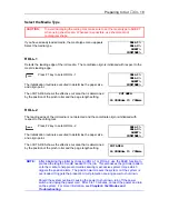
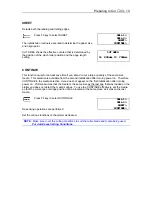
1. Cut the test pattern (Test 1, Test 2, Cutting Pro) in three locations: the far right side,
the center and the far left side of the media.
2. Check the shape of the pattern.
3. Change the condition parameters if needed.
4. Repeat steps 1 through 3 until the test results are satisfactory.
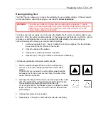
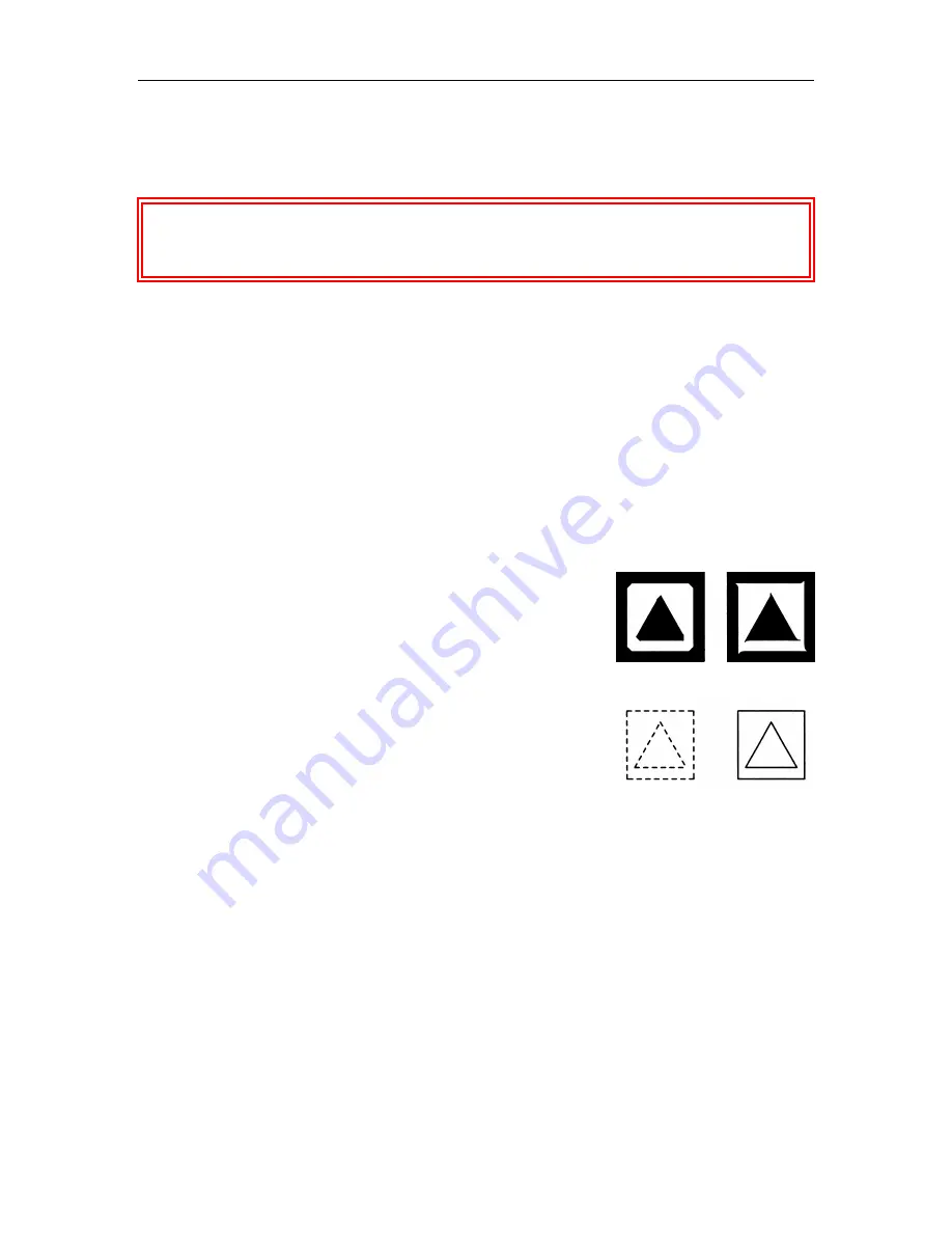
The following illustrations show test pattern results.
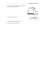
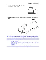
1. Peel the outside triangle off first to view the shape of the
corners. The corner’s shape represents the cutter offset
setting.
If the corners are rounded, the cutter offset value should be
decreased, but if the corners are too sharp, the cutter offset
value should be increased.
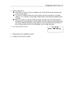
2. Next peel the triangle off the liner to view the depth of the cutter
trail. The depth of the cutter trail represents the blade length.
The best setting creates a light scratch on the liner.
If it is too light and the trail breaks in places, increase the blade
length, but if it so heavy that it cuts the liner, the blade should
be shortened.
3. Change the parameters as needed.
4. Repeat steps 1 through 3 until the test results are satisfactory.
Summary of Contents for Cutting Pro FC4100-100
Page 1: ...cutting pro FC4100 series series USER S MANUAL 1 a...
Page 138: ...Setting the Interface Functions C7 7 Input Output Circuitry Input Output Timing Chart...
Page 147: ...Specifications C8 6 FC4100 100 without Stand FC4100 100 with Stand Standard and Basket Option...
Page 148: ...Specifications C8 7 FC4100 130 without Stand FC4100 130 with Stand Standard and Basket Option...

