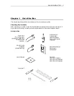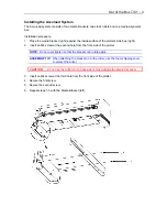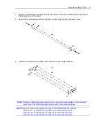
Out of the Box
♦
C1 - 2
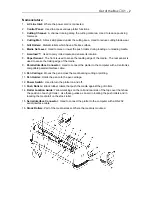
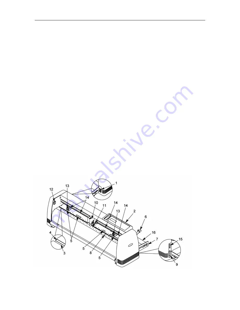
Nomenclature
1.
AC Line Inlet:
Where the power cord is connected.
2.
Control Panel:
Used to access various plotter functions.
3.
Cutting Channel:
A channel running along the cutting mat area. Used to reduce pouncing
tool wear.
4.
Cutting Mat:
A black strip placed under the cutting area. Used to reduce cutting blade wear.
5.
Grit Rollers:
Metallic rollers which have a file like surface.
6.
Media Set Lever:
Used to raise or lower the push rollers during loading or unloading media.
7.
Accuload™:
Used to carry rolled media and ensure its rotation.
8.
Paper Sensor:
The front is used to sense the leading edge of the media. The rear sensor is
used to sense the trailing edge of the media.
9.
Parallel Interface Connector:
Used to connect the plotter to the computer with a Centronics
compatible parallel interface cable.
10.
Pen Carriage:
Moves the pen across the media during cutting or plotting.
11.
Pen Holder:
Holds the pen onto the pen carriage.
12.
Power Switch:
Used to turn the plotter on and off.
13.
Push Rollers:
Black rubber rollers that push the media against the grit rollers.
14.
Roller Location Guide:
Yellow markings on the rail and rear side of the top cover that show
the position of each grit roller. Use these guides as an aid in locating the push rollers and in
locating the media roll on the stock roller.
15.
Serial Interface Connector:
Used to connect the plotter to the computer with a RS-232
serial interface cable.
16.
Stock Rollers:
Part of the media stocker. Where the media is mounted.
Summary of Contents for Cutting Pro FC4100-100
Page 1: ...cutting pro FC4100 series series USER S MANUAL 1 a...
Page 138: ...Setting the Interface Functions C7 7 Input Output Circuitry Input Output Timing Chart...
Page 147: ...Specifications C8 6 FC4100 100 without Stand FC4100 100 with Stand Standard and Basket Option...
Page 148: ...Specifications C8 7 FC4100 130 without Stand FC4100 130 with Stand Standard and Basket Option...

