Out of the Box
♦
C1 - 4
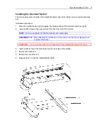
7. Place the media alignment bar in between the tabs of the media brackets that protrude from
the front side from the plotter.
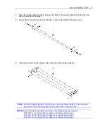
8. Secure the media alignment bar to the tabs at both ends with M4 flat head screws.
9. Install stock rollers into the holes on the rear side of the media brackets.
NOTE:
Be sure to tighten all the screws to ensure accurate media loading. The Accuload™
system may not function properly if even one of the screws are loose.
NOTE:
Be sure to place the plotter on a work surface that will accept a plotter.
FC4100-75: 42 inches (106cm) wide by 19 inches (48cm) deep.
FC4100-100: 55 inches (140cm) wide by 19 inches (48cm) deep.
FC4100-130: 67 inches (170cm) wide by 19 inches (48cm) deep.
Summary of Contents for Cutting Pro FC4100-100
Page 1: ...cutting pro FC4100 series series USER S MANUAL 1 a...
Page 138: ...Setting the Interface Functions C7 7 Input Output Circuitry Input Output Timing Chart...
Page 147: ...Specifications C8 6 FC4100 100 without Stand FC4100 100 with Stand Standard and Basket Option...
Page 148: ...Specifications C8 7 FC4100 130 without Stand FC4100 130 with Stand Standard and Basket Option...


