•
•
(
'
AIR BRAKE VALVES 5H-17
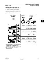
51. Valve Main Body
70. Exhaust Diaphragm
52. Valve Cover
71. Service Piston.
53. Retaining Ring
72.
Service Piston O-Ring
54. Exhaust Cover
73. Spring
55. O-Ring
74. Spring Cage
56. O-Ring
75. Blend Back Piston
57. Valve Spring
76. O-Ring
58. Valve Retainer
77. O-Ring
59. Valve Assembly
78. O-Ring
60. Cap Screw
79. Proportioning Piston
61. Lock .Washer
■
- H
80. O-Ring
62. O-Ring
81. Retaining Ring
63. Relay Piston
82. O-Ring
64. O-Ring
83. Inlet Valve Seat
65. Relay Piston Ring/
85. Spring ,
66. Retaining Ring
86. Sealing Ring
67. Dust Shield
87. Exhaust Cover Screw
68. Exhaust Piston
88. Exhaust Cover
69. Exhaust Piston O-Ring
'
F9040
Figure 22—Bendix Proportioning Relay Valve Components
Inspect
• The interior and exterior of all metal parts for
severe corrosion, pitting, and cracks. Replace as,
needed.
• All non-metallic components for cracks, wear, or
distortion. Replace as needed.
• The bores of the valve main body (51) and valve
cover (52) for deep scuffing or gouges. Replace as
needed.
Install or Connect (Figures 21 and 22)
N O T IC E : F o r s te p s 2 1 a n d 3 4 , s e e “N o tic e ”
o n p a g e 5 H -1 . 1
1. Lubricate all O-rings, seals, and pistons.
2. Lubricate the bores in valve main body and valve
cover with Bendix part number 291126 lubricant.
• Use only new rubber O-rings from the repair kit.
3. O-ring (82) on inlet valve seat (83).
/
4. Small end of spring (85) over rubber on valve (84).
• Make sure the spring coils rest on the valve’s
four tabs.
5. Spring (85) and valve (84) in valve seat (83).
• Make sure the four tabs are in the seat’s bore.
6. Valve (84), seat (83),'. and spring (85) assembly in
proportioning piston (79).
• Large end of spring (85) first.
7. Retaining ring (81) to secure seat (88) in propor
tioning piston (79).
8. O-rings (78 and 80) on proportioning piston (79).
9. O-rings (76 and 77) on blend back piston (75).
10. Small diameter end of proportioning piston (79) in
small diameter end of blend back piston (75).
11. Proportioning piston (79) and blend back piston
(75) to edge of bore in valve cover (52).
12. Spring cage (74) in blend back piston (75) so its
flat side rests against blend back piston (75).
13. O-ring (72) on service piston (71).
14. Spring (73) in cage (74).
15. O-ring (69) on exhaust piston (68).
16. Exhaust diaphragm (70) between six posts of ser-'
vice piston (71).
17. Exhaust piston (68) on service piston (71) with its
six-ribbed side facing service piston (71).
18. Exhaust piston (68) and service piston (71) in valve
cover (52).
^
“
• The proportioning piston (79) and blend back
piston (75) will be pushed ail the way in cover
by exhaust piston (68) and service piston (71).
19. Dust shield (67) in valve cover (52).
20. Retaining ring (66).
21. Exhaust cover (88) and screw (87).
£
Tighten
• Screw (87) to 2.4 N-m (21 in. lbs.).
22. Valve retainer (58) on valve assembly (59).
• The flange of retainer (58) should surround rub
ber portion of valve.
23. Valve assembly (59) in valve main body (51).
24. Valve spring (57) in valve main body (51).
Summary of Contents for C Series 1993
Page 1: ......
Page 12: ...OA 6 GENERAL INFORMATION Figure 11 Allison Transmission I D Location ...
Page 44: ...3B1A 2 POWER STEERING GEAR UNIT REPAIR Figure 1 710 Power Steering Gear ...
Page 62: ......
Page 75: ...3B3 2 POWER STEERING COMPONENTS TRW ROSS ...
Page 121: ...5H 16 AIR BRAKE VALVES Figure 21 Bendix Proportioning Relay Valve Components ...
Page 147: ...5J 10 AIR COMPRESSOR AND GOVERNOR 286 F9051 Figure 18 Bendix BX 2150 Compressor Components i ...
Page 204: ...MODEL 295 TBI UNIT 6C1 3 F7973 Figure 3 Model 295 TBL Unit ...
Page 251: ...6D4 6 37 MT STARTER MOTORS V3022 Figure 8 37 MT Components ...