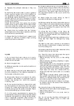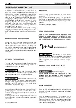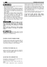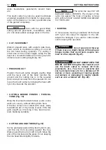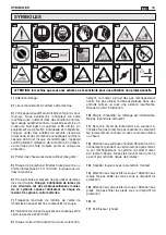
D) MAINTENANCE AND STORAGE
1.
Ensure that all screws and bolts are tightly fas-
tened so that the machine can be used in safety.
Regular maintenance is essential for safety and
a consistently high performance.
2.
Do not use the machine if any parts are dam-
aged or worn. These parts must be replaced, not
repaired. Use original spare parts.The cutting
tools must always bear the manufacturer’s mark
as well as the maximum working speed. Spare
parts that are not the same quality may damage
the machine and jeopardise safety.
3.
Wear thick gloves to remove and refit the cut-
ting tools.
4.
Never store the brush cutter with fuel in the
tank in an environment where petrol fumes could
come into contact with a flame, spark or sources
of extreme heat.
5.
Store the brush cutter in a clean and dry envi-
ronment, out of the reach of children.
6.
Let the motor cool down before it is stored in
any environment.
7.
To reduce the risk of fire, clean any leaves,
grass or excess oil from the brush cutter, espe-
cially its motor, cooling fins, exhaust pipe and
fuel tank.
8.
If the fuel tank has to be drained, do so out-
doors when the motor is cold.
9.
Do not add, remove or modify any machine
components.
This could cause:
– injuries to the operator and other people pres-
ent
– damage to the machine moreover, this invali-
dates the warranty.
10.
During storage or transport, always cover the
blade with its guard in order to prevent acciden-
tal injury.
11.
To respect the environment do not dispose of
oil or petrol by pouring it into the drainage sys-
tem, gutters or into the ground. A local service
station can have oil and fuel recycled in total
safety.
26
SAFETY MEASURES / ASSEMBLY INSTRUCTIONS
EN
ASSEMBLY INSTRUCTIONS
In order to ensure correct
and safe use of the brush cutter, the assem-
bly instructions for protection and safety
components must be followed meticulously.
The manufacturer shall not be held liable if
the brush cutter is used without the afore-
mentioned protection and safety devices.
FRONT HANDGRIP
Brush cutters are normally supplied with the
front handgrip disassembled inside the packag-
ing. Therefore, it must be attached following the
procedure indicated below.
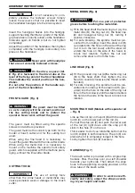
MONO BRUSH CUTTER (Fig. 1)
The front handgrip together with its guard must
be attached. A spacer (E) is positioned on the
!
WARNING!
drive tube, ensuring a minimum distance
between the rear and front handgrips. The front
handgrip must be positioned on the drive tube in
front of this spacer. Fit the square nuts in the
specific seats in the handgrip, then fit the screws
with washers. Tighten the screws gradually and
uniformly. Before fully tightening, adjust the posi-
tion of the front handgrip. Terminate by tighten-
ing the screws to the same degree.
Do not modify or damage
the spacer. Comply with the minimum dis-
tance between handgrips.
DUPLEX BRUSH CUTTER (Fig. 2)
The handlebar-type front handgrip must be
fixed. Use handle A (fig.2) to unscrew and loosen
the handgrip blocking system.
!
WARNING!
Summary of Contents for BJ 250
Page 2: ......
Page 5: ...3 19 21 22 24 25 28 29 17 23 18 20 26 A 27 E...
Page 6: ...4...
Page 119: ...EL 117...
Page 122: ...1 2 3 4 15 5 6 B 1 2 3 120 EL...
Page 123: ...3 4 5 STOP 6 7 C 1 2 3 4 5 6 7 8 3 4 9 10 15 11 15 12 13 14 121 EL...
Page 124: ...15 16 D 1 2 3 4 5 6 7 8 9 10 11 122 EL MONO 1 barrier DUPLEX 2 2...
Page 125: ...A E 2 3 2 4 a C D b H A 5 a C b H A 6 A B C D E D E F D E G 7 123 EL...
Page 126: ...60 2 50 1 2 2 di olio SYNTETIC OIL 2T 4 25 1 4 124 EL...
Page 127: ...8 stop START 9 1 2 3 9 4 10 6 7 5 10 2 CLOSE RUN I CLOSE 10 11 RUN I 10 125 EL...
Page 128: ...12 STOP 13 T 126 EL...
Page 129: ...OFF STOP 15 30 4 60 90 14 3 2 cm 15 Tap Go 16 17 127 EL...
Page 130: ...18 19 20 30 21 15 22 128 EL...
Page 131: ...3 4 23 24 25 A B C 3 4 26 1 A 2 3 4 27 1 0 6 mm 025 2 3 12 15 Nm 28 STOP 1 E 29 2 129 EL...
Page 132: ...1 2 3 4 5 5 6 7 1 8 1 2 3 4 5 130 EL...
Page 133: ...EL 131...
Page 263: ...RU 261...
Page 266: ...A A 1 1 2 2 3 3 4 4 15 5 5 6 6 1 1 2 2 3 3 264 RU...
Page 269: ...A E E 2 2 3 3 4 4 a a A B C D E A 5 5 a a A B C A 6 6 D D F D E G 7 7 267 RU...
Page 271: ...8 START 9 1 2 K K K 3 9 4 10 6 7 5 10 2 K I K 10 K 11 I 10 K 269 RU...
Page 272: ...1 12 2 STOP 13 270 RU...
Page 273: ...S ST TO OP P 1 15 5 3 30 0 4 60 90 14 2 15 Tap Go 16 17 271 RU...
Page 274: ...18 1 19 9 2 20 0 30 2 21 1 1 15 5 2 22 2 272 RU...
Page 275: ...3 3 4 4 23 24 25 3 4 2 26 6 1 A 2 3 4 2 27 7 1 0 6 2 3 12 15 Nm 2 28 8 STOP 1 29 2 273 RU...
Page 276: ...1 2 3 4 5 5 6 7 1 8 1 2 3 4 5 274 RU...
Page 295: ......


