Falcon 4M30, User Manual
The Falcon 4M30 is a high-performance quadcopter perfect for beginners and experienced flyers alike. For a detailed understanding of its features and functions, make sure to download the free User Manual from manualshive.com. This comprehensive manual will guide you through setup, operation, and troubleshooting with ease.
Share
Download


Reviews:
No comments
Related manuals for 4M30

SK6288GKOC-L
Brand: Schäfter+Kirchhoff Pages: 32
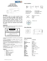
XC700CM(DN)
Brand: XENO Pages: 2
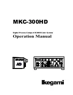
MKC-300HD
Brand: Ikegami Pages: 35

WDEM-7680LPDN-IO
Brand: Okina Pages: 36

ID-650VDN
Brand: Genesis CCTV Pages: 3
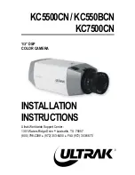
KC5500CN
Brand: Ultrak Pages: 36
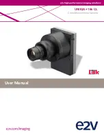
UNIIQA+ 16k CL
Brand: e2v Pages: 50
LI-1080PTZOV
Brand: Leopard Pages: 58
VC-54B
Brand: E-SYSTEM Pages: 4
FastCamera13
Brand: FastVision Pages: 52
VC5000
Brand: Vicon Pages: 20
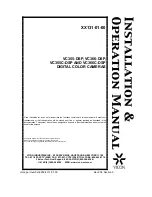
VC355-DSP
Brand: Vicon Pages: 21
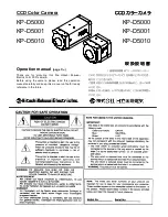
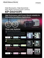
KP-D5000
Brand: Hitachi Pages: 54
KP-D5010
Brand: Hitachi Pages: 2
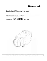
GP-MH310 series
Brand: Panasonic Pages: 43
WV-CF112E
Brand: Panasonic Pages: 2
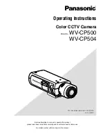
WV-CP500 series
Brand: Panasonic Pages: 35
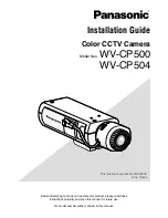
WV-CP500 series
Brand: Panasonic Pages: 32


