manualshive.com logo in svg
background image


MKC-300HD 


Digital Process Compact 3CMOS Color Camera 


Содержание MKC-300HD

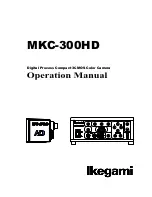
Страница 1: ...MKC 300HD Digital Process Compact 3CMOS Color Camera ...

Страница 2: ...The copyright of the software made for this product is in Ikegami Tsushinki Co Ltd It forbids to reproduction a change and so on about DN 27466 ...

Страница 3: ...hock may be caused Do not make alterations to the unit A fire or electric shock may be caused When installing the unit Do not set the unit in an unstable place It may drop or turn down causing an injury Do not connect to any other equipment than specified A fire or electric shock may be caused When fixing the unit ask a professional contractor Whenfixingtheunit dosoinaccordancewiththe specified pr...

Страница 4: ...ed by one person it may turn down or drop some times causing an physical damage to the waist or hand or a physical injury Take preventive measures against the overturn of the unit due to an earthquake or sudden shock As the unit may overturn and cause a physical injury take preventive measures against the overturn Maintenance Turn off the power switch and pull out the power plug before maintenance...

Страница 5: ... should be at least 30 Electrical fast transient burst IEC61000 4 4 2kV for power supply lines 1kV for input output lines 2kV for power supply lines 1kV for input output lines Main power quality should be that of a typical commercial or hospital environment Surge IEC61000 4 5 1kV differential mode 2kV common mode 1kV differential mode 2kV common mode Main power quality should be that of a typical ...

Страница 6: ...etermined by an electromagnetic site survey a should be less than the compliance level In each frequency range b Interference may occur in the vicinity of equipment marked with the following symbol NOTE 1 At 80 MHz and 800 MHz the higher frequency range apply NOTE 2 These guidelines may not apply in all situations Electromagnetic propagation Is affected by absorption and reflection from structures...

Страница 7: ...etting Auto White Balance 13 4 Menu Operation 14 Operation Method 14 Video Adjust 15 AE Mode 16 DTL Set 17 Video Setting 18 Auto Adjust 19 Scene File 20 Foot Switch Mode 21 Inverse 22 STILL Setting 22 Date Time Adjust 23 DVI Setting 23 Down Converter setting 24 Miscellaneous 24 Version Info 25 5 Specification 25 Ratings 25 Performance 26 Functions 26 6 External Appearance 28 Camera Head Unit mm 28...

Страница 8: ...unt for connecting the lens and microscope adapter Lens Connector Used to connect the Iris cable of the special microscope adapter and 1 3 C mount lens Lens Connector Pin Assignment Connector Type HR10A 7R 4S 1 12V 2 GND 3 IRIS 4 N C Camera Connector Used to connect to the Camera connector of CCU with the Camera cable DN 27466 ...

Страница 9: ... power When this switch is turned on the picture is output in the state where power was last turned off However the state of still screen picture is not 16 Arrow Key 2 Auto White Balance Switch 3 Color Bar Switch 7 Detail Enhancement Switch 8 Freeze Picture Switch 4 Electronic Shutter Switch 9 Picture Save Switch 6 Iris Control Switch 13 Video Level Indicator 12 Brightness Control Volume 11 Blue P...

Страница 10: ... etc of the color monitor Electronic Shutter Switch To keeps the video signal output level constant by controlling shutter speed automatically Automatic switching from 1 100 seconds to 1 10 000 seconds When this switch is used with 5 Automatic Gain Control Switch an optimum picture can be output regardless of the brightness of an object Automatic Gain Control Switch When shooting a dark scene from...

Страница 11: ...Electronic Shutter and 5 Automatic Gain Control are operative When using an auto iris adjustable microscope adapter or an auto iris lens it works as a fine control function with 6 Iris Control Switch turned on It can be manually controlled when this switch turned off Video Level Indicator Indicate the video output level When LED of the video level indicator lights up red it means that the video ou...

Страница 12: ...ed through the menu When selecting an item you want to set on the menu move cursor by clicking Arrow Keys and changing the contents of the item you want to set choose the value you have set by clicking Arrow Keys USB Connector Used to connect the USB storage for saving a still picture DN 27466 ...

Страница 13: ...2ch of HD SDI signal Connect a Video Cable Option to a HD SDI input interfaced monitor Genlock Input Connector To use in phase synchronization with other systems Connect a synchronized signal from another system Equivalent to Three Phase Synchronization HD and Two Phase Synchronization SD 10 Foot Switch Connector 3 Genlock Input Connector 1 Camera Connector 4 HD RGB Output Connector 2 HD SDI Outpu...

Страница 14: ... interfaced monitor SD RGB Output Connector Output SD RGB video signal YPbPr video signal output is also available by changing the setting on the menu Refer to Video Setting Page 19 for further detailed operations Connect a RGB Video Cable Option to a RGB input interfaced monitor USB Connector Connect USB storage device DVI D Output Connector Connect a DVI D Cable Option to a DVI D input interface...

Страница 15: ...side CAUTION for USB Connection The USB output of this camera is provided to record picture signals at JPEG or BMP format only into an external USB storage device and it has no function to exchange the control signal from external equipment When making USB connection between this camera and a USB storage device the USB output may not operate properly according to equipment For USB storage device o...

Страница 16: ... MKC 300HD when you connect or disconnect the camera cable If the CCU is turned on it may cause the fault of MKC 300HD NOTE Phenomenon on video image MKC 300HD may happen following phenomenon on its video image It is not failure but it is because of employing CMOS sensor When its sensitivity gain is going up and or when it is slow shutter mode it may appear high lighting dots In case under high te...

Страница 17: ...n Auto White Balance Switch Shoot a white photographic object on the screen largely Set the picture level to such a degree that the white photographic object is not excessively bright and press AWB button Auto White Balance appears on the monitor screen When auto white balance is finished OK appears Auto White Balance Auto White Balance O K When the video level is low Too Dark appears If Auto Whit...

Страница 18: ... monitoring screen on which various camera functions can be set MENU Video Adjust AE Mode DTL Set Video Setting MENU Auto Adjust Scene File Foot Switch Mode Inverse STILL Setting Date Time Adjust DVI Setting Down Converter setting Miscellaneous Version Info 2 Select an item by Arrow Keys on the front panel of CCU and press SET switch to define the mode Pressing Menu switch on the front panel of CC...

Страница 19: ... master pedestal value by Arrow Keys It is not used during ordinary operation Gain Offset Red Used to change the level of red by Arrow Keys switches It has the same function as 10 Red video volume ref page5 on the front panel of CCU Blue Used to change the level of blue by Arrow Keys switches It has the same function as 11 Blue video volume on the front panel of CCU DN 27466 ...

Страница 20: ...of 4 Electronic Shutter Switch ref page5 and 5 Automatic Gain Control Switch on the Front Panel of CCU are turned on It has the same function as 12 Brightness Control Volume on the Front Panel of CCU AE Speed Used to select the response rate of the Electronic Shutter and Automatic Gain Control from among Middle Fast and Slow AE Sensitivity To adjust the tolerance level ratio to the target level ac...

Страница 21: ... the maximum shutter speed while Automatic Gain Control is operative DTL Set Used to adjust detail enhancement DTL Set QUIT DTL ON DTL Gain 10 Skin DTL Gain 25 DTL Set it to ON usually Used to turn on an off whole picture detail enhancement When it is set to OFF the detail enhancement switch on the Front Panel of CCU is not operative DTL Gain To adjust the detail enhancement level Skin DTL Gain To...

Страница 22: ...Format 1080i 59 94 Aspect 16 9 Analog Output YPbPr Format Select the video signal format among 1080i 59 94 1080i 50 720P 59 94 and 720P 50 Aspect Select Picture Aspect ratio from 16 9 and 4 3 Analog output Select the picture format for analogue video output from RGB and YPbPr DN 27466 ...

Страница 23: ...If this adjustment is not performed with the lens are fully closed it will adversely affect the picture output of the camera No problem will occur even if it is not used during ordinary operation Auto White Shade Used for automatic white shading correction Use it when there is a large difference between brightness near the center and brightness in the neighboring part DN 27466 ...

Страница 24: ...e 2 Store Scene3 When setting is changed the data can be saved in Scene file 3 Store Scene4 When setting is changed the data can be saved in Scene file 4 Load Factory Default Used to read the factory default data Used to cancel the changed setting To execute select Start and the press SET switch Auto Store When setting is changed this function is used to set whether or not the data is saved at the...

Страница 25: ...rescein Frip Mirorr and Rotate Foot Switch 2 Select a function of the green foot switch from among Screen control Freeze Save Still picture store Scene File Fluorescein Frip Mirorr and Rotate Foot Switch 3 Select a function of the third foot switch from among Screen control Freeze Save Still picture store Scene File Fluorescein Frip Mirorr and Rotate Foot Switch 4 Select a function of the fourth f...

Страница 26: ...ideo image Bottom to Top STILL Setting Used to set the quality of a still picture to be stored in an external device USB memory STILL Setting QUIT Format JPEG JPEG Factor 4 Format To determine the format of the still picture Select JPEG format or Bitmap format JPEG Factor To determine the compression rate of JPEG format Higher number means increasing compression rate and the file size becomes smal...

Страница 27: ...uth 1 Day 15 Hour 13 Minute 00 Adjust Ready When Date and Time have been changed move to Adjust and select Start before quit the menu DVI Setting To set DVI output signal format DVI Setting QUIT Format 1080I Format To set DVI output signal format from 1080P and 1080I DN 27466 ...

Страница 28: ...om RGB format and YCbCr Miscellaneous Used for other settings Miscellaneous QUIT Initialize ex Scene Ready Media Format Ready Cable Length 15m Bar Mode Multi Center Marker OFF Initialize ex Scene To read the factory default data expect for Scene file setting data Media Format To execute initial format USB storage device Cable Length To select the camera cable length Bar Mode To display Color Bar s...

Страница 29: ... pixels CMOS x 3 Effective Pixels 1920 H 1080 V Lens Mount C Mount Video Output 2 1 Interlace 1125 Line 59 94 Field 30 Frame Aspect Ratio H16 V9 Output Video Signal HDTV Output Analog Y Pb Pr D sub 1 Line HD SDI BNC 2 Lines DVI 1920x1080i p 1 Line SDTV Output Down Convert Composite VBS BNC 1 Line D sub 1 Line S VIDEO S Terminal 1 Line D Sub 1 Line RGB D sub 1 Line Input Video Signal External Sync ...

Страница 30: ...AC100V to 240V 10 Power Consumption 100VA Operating Temperature 0 C to 40 C Storage Temperature 10 to 60 Dimensions Weight Camera Head W34xH40xD40mm without protrusion 100g or less CCU W210xH80xD300mm without protrusion 2 5kg or less Accessories AC Power Cable 10A 125V KP320 KS31 SJT 3 10A 250V KP4819D KS31A GTCE 3 USB memory Performance Resolutions Horizontal 1000TV Lines S N Ratio 54dB γ and Det...

Страница 31: ...w Shutter Up to 1 4 seconds slow shutter speed available Paint R chanel B chanel Level Adjustable AE Level Exposure Level Adjustable Video Level Indicator 7 steps Color Bar Built in Photometry Area Selectable in Menu 4 3 Video Output 4 3 Side Cut Still Image Capture 1920x1080 dots still picture on a USB memory JPEG or BMP selectable Others Various set up from On Screen Menu DN 27466 ...

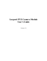
Страница 32: ...28 DN 27466 6 External Appearance Camera Head Unit mm CCU ...

Страница 33: ...29 DN 27466 ...

Страница 34: ...hed by Ikegami Tsushinki Co Ltd It forbids to copy it without notice and to reproduce it about a part of this manual or all as for any method as well without taking the assent of Ikegami Tsushinki Co Ltd A specification and an appearance are sometimes changed without notice Editied by Chuo seizu Co Ltd ...

Страница 35: ...hone 03 5700 1111 Fax 03 5700 1137 Ikegami Electronics U S A Inc 37 Brook Avenue Maywood New Jersey 07607 U S A Phone 201 368 9171 Fax 201 569 1626 Ikegami Electronics Europe GmbH Ikegami strasse 1 41460 Neuss 1 F R Germany Phone 02131 123 0 Fax 02131 102820 DN 27466 ...

Отзывы: