Chapter 10: Auxes and Variable Groups
87
Pre-Fader
This pickoff point is post-HPF, post-EQ Dynamics,
and Channel Inserts, post-Mute, and pre-Fader. The Aux or
Variable Group Send is affected by the channel mute.
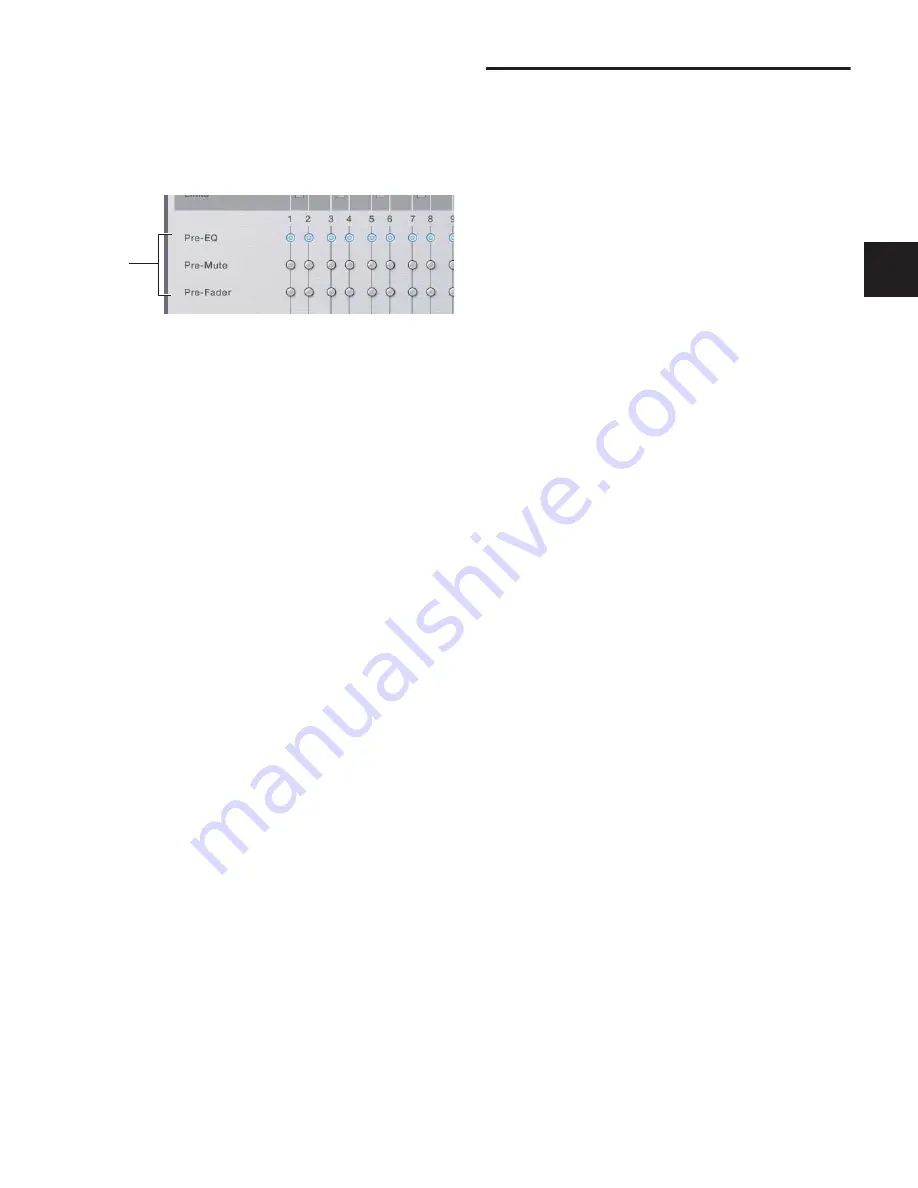
To set the Pre pickoff point for an Aux or Variable Group Send:
1
Go to the Options page and click the Busses tab.
2
Select a Pre pickoff point for any of the busses or linked bus
pairs by clicking the Pre-EQ, Pre-Mute, or Pre-Fader button.
To activate a Pre pickoff point for an Aux Send or Variable Group
Send on-screen:
1
Go to the Inputs page and target the channel with the pick-
off point you want to activate by clicking its on-screen chan-
nel fader strip.
2
Do any of the following:
• To activate an Aux Send Pre pickoff, click the correspond-
ing Pre button in the Aux Sends section.
– or –
• To activate a Variable Group Pre pickoff, click the Var
Groups button in the Bus Assign section to display Var
Groups, then click the corresponding Pre button in the
Var Groups section.
When the Pre button is lit, the selected Pre pickoff point is
used. When the Pre button is off, the pickoff point is
Post-Fader.
Classifying Auxes and Variable Groups for
Snapshots
You can classify Aux Sends and Variable Group Sends as
mon-
itor sends
(“Mon”) or as
effects sends
(“FX”) for the purposes of
scoping and safing each type separately in snapshots. See
“Classifying Auxes and Variable Groups” on page 192.
Assigning Inputs to Aux Busses and
Variable Group Busses
You can send signals from any Input Channel or FX Return to
any number of Aux busses or Variable Groups simultaneously.
Aux Send and Variable Group Send level controls provide a
gain range of –INF to +12 dB.
To assign one or more channels to an Aux send or Variable Group
bus:
1
Press the Auxes 1–8 or Auxes 9–16 switch to bank the Out-
put faders to those Aux busses. For Variable Groups, press the
Groups switch.
2
Press the Select switch in the Output strip for the Aux (1–8,
or 9–16) or Variable Group (1–8) to which you want to assign.
3
Press the Multi Assign switch near the Output encoders.
While engaged, the Multi Assign and output Select switch
LEDs flash.
4
Press the Select switch on the channels you want routed to
the selected Aux send.
5
Press the Multi Assign switch again to confirm the action.
– or –
■
Select another Aux to confirm the current assignment but
remain in Multi Assign mode for the newly targeted bus.
Routing Signals to Mono Aux and Variable
Group Busses
To route channels to an unlinked (mono) Aux bus or Variable
Group bus from the Input section:
1
Do one of the following to select input channels:
• Target the channel you want to send to an Aux bus by
pressing its Select switch.
– or –
• Hold the Multi Select switch, then press the Select
switches on each of the channels you want to send to an
Aux bus.
2
Do one of the following:
• Press an Encoder assign Send switch 1–2 through 15–16
to display Aux Sends on the input channels.
– or –
• Press the Var Groups switch in the ACS Bus Assigns sec-
tion. This displays Variable Group Sends on the input
channel encoders and the ACS Aux Send controls.
Setting Aux bus pickoff points
Pickoff
point
options
Summary of Contents for D-Show Profile
Page 10: ...D Show Profile Guide x ...
Page 11: ...Part I Overview and Installation ...
Page 12: ......
Page 16: ...D Show Profile Guide 6 ...
Page 32: ...D Show Profile Guide 22 ...
Page 33: ...Part II System Description ...
Page 34: ......
Page 50: ...D Show Profile Guide 40 ...
Page 58: ...D Show Profile Guide 48 ...
Page 67: ...Part III Signal Routing ...
Page 68: ......
Page 94: ...D Show Profile Guide 84 ...
Page 102: ...D Show Profile Guide 92 ...
Page 110: ...D Show Profile Guide 100 ...
Page 134: ...D Show Profile Guide 124 ...
Page 135: ...Part IV Processing ...
Page 136: ......
Page 144: ...D Show Profile Guide 134 ...
Page 171: ...Part V Shows ...
Page 172: ......
Page 180: ...D Show Profile Guide 170 ...
Page 204: ...D Show Profile Guide 194 ...
Page 227: ...Part VI Specifications ...
Page 228: ......
Page 236: ...D Show Profile Guide 226 D Show Output Signal Flow Diagram Version 1 3 07 07 05 ...
Page 245: ...Part VII Reference ...
Page 246: ......
Page 258: ...D Show Profile Guide 248 ...
Page 269: ......


