Chapter 4: Basic Commands and Modes
37
To reset Threshold on-screen:
1
Select an input or output channel on-screen.
2
Do one of the following:
• Right-click the Threshold encoder on-screen and choose
Reset.
– or –
• Hold the Default switch on the control surface and click
the Threshold encoder on-screen.
Fine Switch
The Fine (Ctrl) switch lets you adjust controls (except for fad-
ers) on the control surface or on-screen with maximum reso-
lution. For example, if by default a controls adjusts a parame-
ter in units of 1 dB, the Fine switch lets you adjust in units of
0.1 dB.
To adjust a control with fine resolution:
■
Press and hold the Fine switch while moving a control. The
display associated with the adjusted control will show the val-
ues changes at the corresponding resolution.
Momentary and Latching Modes
The Fine switch supports momentary and latching operation.
Momentary
In momentary mode, the Fine switch stays in ef-
fect for as long as you hold down that modifier switch.
Latching
In latching mode, the Fine switch stays in effect until
you explicitly clear its active state.
To use the Fine switch in Momentary mode:
1
Press and hold the Fine switch.
2
Adjust a channel, parameter, or processor.
3
Release the Fine switch.
To use the Fine switch in latching mode:
1
Double-press the Fine switch. The switch LED lights.
2
Select or adjust one or more channels, parameters, or pro-
cessors.
3
Press the Fine switch again to exit latching mode.
User
The User switch is reserved for future use.
Software Screen Pages and Tabs
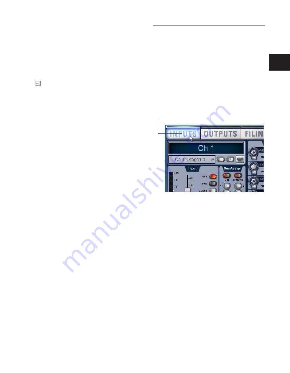
Viewing Pages
To view a page, do one of the following:
■
Press a View Mode switch.
– or –
■
Click the page name at the top of the screen.
When additional tabs are available for a page, go to those tabs
by pressing the corresponding View Mode switch again to cy-
cle through the tabs on that page, or by clicking their names
on-screen.
To reset a parameter using only the keyboard and trackball,
press Alt+the on-screen control.
Viewing pages
Click page name to display
Summary of Contents for D-Show Profile
Page 10: ...D Show Profile Guide x ...
Page 11: ...Part I Overview and Installation ...
Page 12: ......
Page 16: ...D Show Profile Guide 6 ...
Page 32: ...D Show Profile Guide 22 ...
Page 33: ...Part II System Description ...
Page 34: ......
Page 50: ...D Show Profile Guide 40 ...
Page 58: ...D Show Profile Guide 48 ...
Page 67: ...Part III Signal Routing ...
Page 68: ......
Page 94: ...D Show Profile Guide 84 ...
Page 102: ...D Show Profile Guide 92 ...
Page 110: ...D Show Profile Guide 100 ...
Page 134: ...D Show Profile Guide 124 ...
Page 135: ...Part IV Processing ...
Page 136: ......
Page 144: ...D Show Profile Guide 134 ...
Page 171: ...Part V Shows ...
Page 172: ......
Page 180: ...D Show Profile Guide 170 ...
Page 204: ...D Show Profile Guide 194 ...
Page 227: ...Part VI Specifications ...
Page 228: ......
Page 236: ...D Show Profile Guide 226 D Show Output Signal Flow Diagram Version 1 3 07 07 05 ...
Page 245: ...Part VII Reference ...
Page 246: ......
Page 258: ...D Show Profile Guide 248 ...
Page 269: ......


