D-Show Profile Guide
200
Creating Triggers
Each event can have up to eight triggers. You create new trig-
gers by selecting them from the Add pop-up menu. Once
added, you can edit triggers and their properties to customize
them.
Adding Triggers to an Event
To add a trigger:
1
Select an event in the Event List, or create a new one. (For
details, see “Selecting Events” on page 198, and “Creating
Events” on page 198.)
2
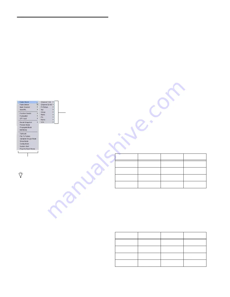
Click the ADD pop-up menu in the Trigger list and select an
action type. The selected trigger type is added to the Trigger
list for the currently selected event, with its default properties.
Editing Trigger Type and Properties
To edit the trigger and its properties:
1
Double-click the trigger row in the list. Or right-click the ac-
tion item and choose Edit.
2
Choose a new Trigger Type, or edit any of the available prop-
erties in the row for that trigger. Properties vary depending on
the type of trigger selected (not all trigger types have editable
properties).
Logical Operators for Triggers
An individual trigger is considered to be “true” when the func-
tion described by its type and properties takes place, such as
while a footswitch is actually pressed, or a fader is raised above
its trigger threshold.
A trigger is considered to be “false” (or, not occurring) when-
ever its function and properties are not met, such as when a
footswitch is not being pressed, or while a fader remains be-
low its assigned trigger threshold.
When an event includes multiple triggers, a logical operator
(OR, AND, XOR) must be chosen from the Operators pop-up
menu. (The default Operator is OR.)
The logical operator has no effect when the Triggers list in-
cludes only one item.
To choose a logical operator for the current event:
1
Select the desired event to display its assigned triggers.
2
Click the Operators pop-up menu (by default, this pop-up
menu displays “OR”) and choose AND, OR, or XOR.
Only one logical operator is permitted per event, and this op-
erator applies to all triggers within the event. It is not possible
to use a mix of logical operators within an event.
Examples of Logical Operators
Logical operators determine the precise state required in order
for an event to occur as shown in the following tables:
OR
At least one of the triggers must be true. The following ta-
ble shows the effect of OR on events with multiple triggers. In
the table, 0 indicates a false condition (not occurring) and 1
indicates a true condition (occurring).
When using OR, if one or more (but not all) of the triggers go
false, the event logic is only acted on again when all triggers
evaluate to false (result = 0).
AND
All triggers must be true. The following table shows the
effect of AND on events with multiple triggers. In the table, 0
indicates a false condition (not occurring) and 1 indicates a
true condition (occurring).
Add Triggers
For a list of available trigger types, see “Trigger Types” on
page 206.
Trigger Types
Channels and Busses
Example truth table for OR, showing two triggers
Trigger A
Operator
Trigger B
Result
0
OR
0
0
0
OR
1
1
1
OR
0
1
1
OR
1
1
Example Truth table for AND showing two triggers
Trigger A
Operator
Trigger B
Result
0
AND
0
0
0
AND
1
0
1
AND
0
0
1
AND
1
1
Summary of Contents for D-Show Profile
Page 10: ...D Show Profile Guide x ...
Page 11: ...Part I Overview and Installation ...
Page 12: ......
Page 16: ...D Show Profile Guide 6 ...
Page 32: ...D Show Profile Guide 22 ...
Page 33: ...Part II System Description ...
Page 34: ......
Page 50: ...D Show Profile Guide 40 ...
Page 58: ...D Show Profile Guide 48 ...
Page 67: ...Part III Signal Routing ...
Page 68: ......
Page 94: ...D Show Profile Guide 84 ...
Page 102: ...D Show Profile Guide 92 ...
Page 110: ...D Show Profile Guide 100 ...
Page 134: ...D Show Profile Guide 124 ...
Page 135: ...Part IV Processing ...
Page 136: ......
Page 144: ...D Show Profile Guide 134 ...
Page 171: ...Part V Shows ...
Page 172: ......
Page 180: ...D Show Profile Guide 170 ...
Page 204: ...D Show Profile Guide 194 ...
Page 227: ...Part VI Specifications ...
Page 228: ......
Page 236: ...D Show Profile Guide 226 D Show Output Signal Flow Diagram Version 1 3 07 07 05 ...
Page 245: ...Part VII Reference ...
Page 246: ......
Page 258: ...D Show Profile Guide 248 ...
Page 269: ......


