Chapter 14: Solo and Monitor Busses
115
2-Track Return
If 2-Track input is enabled, any signal from those inputs is
sent to the Monitor bus. If Mix to Monitors is enabled, the
2-Track input overrides it so you can monitor the 2-Track re-
turn without having to disable Mix to Monitors.
Mix to Monitors
The Main mix (the signal present on the Main busses) can be
sent to the Monitor bus.
Assignable Monitor Output
The Monitor bus can be routed to hardware outputs and to
bus-fed plug-ins.
Hardware Outputs
For routing to hardware outputs, the Moni-
tor (Solo) bus outputs are available in the Mains tab of the
Patchbay Outputs page. Monitor bus outputs are assignable to
any number of physical outputs on the Stage Rack or FOH
Rack in addition to the dedicated Monitor outputs on the
FOH Rack. Use this capability to route monitor outputs to
multiple cue stations (in-ear mix and wedge mix), or to an
outboard analyzer.
Bus-Fed Plug-Ins
For routing to bus-fed plug-ins, the Monitor
bus appears as a choice in the plug-in routing selector. This
lets you route the Monitor bus to a bus-fed stereo plug-in such
as an onboard analyzer. Plug-ins can not be inserted on the
Monitor bus.
Routing the Monitor Bus to Additional Outputs
To route the Monitor bus to additional outputs:
1
Go to the Outputs page and click the Mains tab.
2
Click in the grid to assign the Monitor output to the desired
destination.
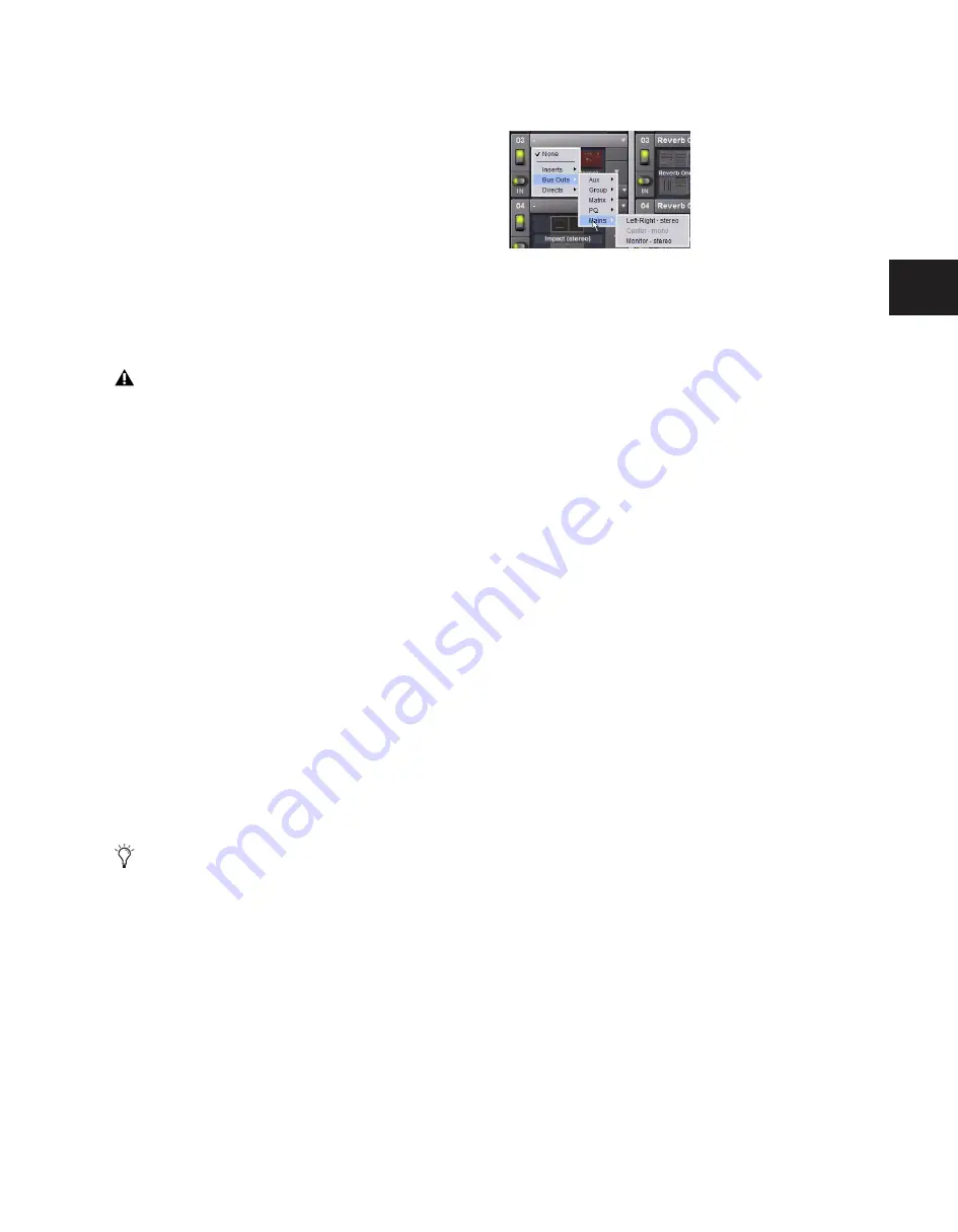
Routing the Monitor Bus to Plug-Ins
To route Monitor output to a bus-fed plug-in:
1
Go to the Plug-Ins screen.
2
Make sure the desired stereo plug-in is installed and as-
signed to a rack slot.
3
Click the Plug-In Input selector at the top of the correspond-
ing rack slot, and choose Bus Outs > Mains > Monitor - stereo.
Sending the Main Mix to the Monitor Bus
Monitor Output from an L-C-R Main Mix
The stereo Mix to Monitors signal is derived from the L–C–R
Main mix by adding a –3 dB signal from the Center channel to
the Left and Right monitor channels.
Monitor Output from an L–R+M Main Mix
In a L–R+M Main mix, only the Left and Right channels are
heard in the Solo bus.
To send the Main mix to the monitors:
1
Do one of the following:
• Press the Mix to Monitors switch in the Mains section.
– or –
• Go to the Options > Busses tab and select the Mix to
Monitors option.
2
Turn the Monitor Speakers knob or the Headphones knob to
adjust the corresponding output level.
Adjusting Solo Bus Level
Solo bus monitoring levels are controlled by the Level Trim
knob in the Solo/PFL section, and the on-screen Level Trim
control. The trim amount is adjustable over a range of –20 dB
to +20 dB.
To trim the Solo bus level:
1
Solo a channel or press a Key Listen switch.
2
Do one of the following:
• Turn the Level Trim knob to control the amount of signal
sent to the Monitor bus.
– or –
• Go to the Options > Busses tab and adjust the Level Trim
setting in the Solo and Monitor Operations section.
These feeds are in addition to the existing, dedicated Mon-
itor outputs on the FOH Rack, and are taken post-Monitor
Speakers control and post-Monitor bus Delay.
Solo In Place, when engaged, is simultaneously routed to
the Mains and Monitor busses.
Assigning monitor output to a bus-fed plug-in
Summary of Contents for D-Show Profile
Page 10: ...D Show Profile Guide x ...
Page 11: ...Part I Overview and Installation ...
Page 12: ......
Page 16: ...D Show Profile Guide 6 ...
Page 32: ...D Show Profile Guide 22 ...
Page 33: ...Part II System Description ...
Page 34: ......
Page 50: ...D Show Profile Guide 40 ...
Page 58: ...D Show Profile Guide 48 ...
Page 67: ...Part III Signal Routing ...
Page 68: ......
Page 94: ...D Show Profile Guide 84 ...
Page 102: ...D Show Profile Guide 92 ...
Page 110: ...D Show Profile Guide 100 ...
Page 134: ...D Show Profile Guide 124 ...
Page 135: ...Part IV Processing ...
Page 136: ......
Page 144: ...D Show Profile Guide 134 ...
Page 171: ...Part V Shows ...
Page 172: ......
Page 180: ...D Show Profile Guide 170 ...
Page 204: ...D Show Profile Guide 194 ...
Page 227: ...Part VI Specifications ...
Page 228: ......
Page 236: ...D Show Profile Guide 226 D Show Output Signal Flow Diagram Version 1 3 07 07 05 ...
Page 245: ...Part VII Reference ...
Page 246: ......
Page 258: ...D Show Profile Guide 248 ...
Page 269: ......


