D-Show Profile Guide
102
Patching Grid
The Patching Grid shows hardware I/O across the top, and
D-Show channels down the left side for the currently selected
I/O and Channel type. The grid squares represent patch points
between hardware I/O and D-Show channels.
You can customize the routing of hardware I/O to D-Show
channels by clicking and dragging in the corresponding
squares in the grid. For complete patching instructions see
“Routing Channels in the Patchbay” on page 104.
By default, inputs are routed in a 1-to-1 pattern to D-Show in-
put channels resulting in Stage Rack inputs 1–48 appearing on
D-Show Input Channels 1–24 (Bank A) and 25–48 (Bank B).
Channel Controls
These controls mirror the controls for the currently selected
channel. For example, when showing Inputs, the Channel
controls let you adjust Input Channel gain, polarity, phantom
power, HPF, and basic level without leaving the Patchbay.
Channel Direct Outs
The channel area in the Patchbay provides access to all Direct
Out controls.
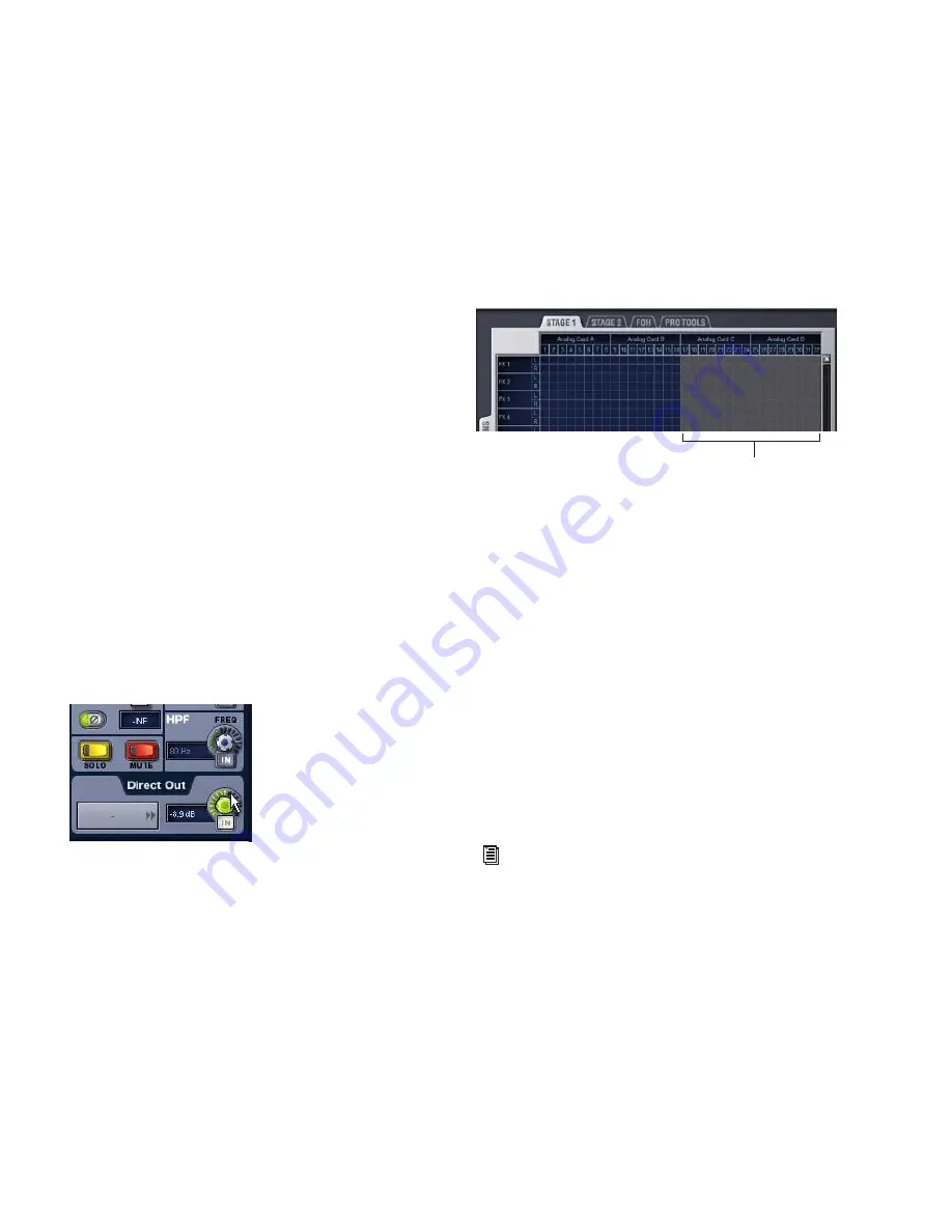
To adjust Direct Output level from the Patchbay:
1
In the Inputs or Outputs page, select a channel.
2
Click the Direct Out routing selector to go to the Patchbay.
3
In the Patchbay channel controls, adjust the on-screen Di-
rect Output encoder.
Visual Indicators and Displays
The Patchbay uses the following visual display conventions in
all its pages and tabs.
Unavailable I/O
The Patchbay displays hardware tabs for all possible configu-
rations, even if your system does not include any expansion
options.
The Patchbay indicates I/O that is offline or unavailable by
graying out the columns beneath that device.
Hardware I/O channels appear as unavailable whenever the
required hardware is not present or offline. Hardware includes
Stage Racks, FOH Racks, and audio cards installed in them. A
hardware device is offline if it is not powered on, not commu-
nicating with the system, or it represents an expansion option
that is not installed.
Even if hardware is unavailable, you can still assign routing
from or to it in the Patchbay. Unavailable I/O appears
itali-
cized
in all routing pop-up lists (such as the Inputs and Out-
puts screens).
Hardware I/O availability is saved with Show files, which store
the status of hardware at the time of the last save performed at
the system.
The D-Show Standalone software provides additional display
options for hardware I/O (including unavailable I/O).
Assigned I/O
When a hardware I/O channel is assigned, its channel number
is darkened in all Patchbay screens. This lets you see which
hardware channels are in use without having to switch back
and forth between Patchbay screens. You can also use the
dimmed column number indicator to jump to the Patchbay
tab for the existing assignment (for more information, see
“Shortcut for Locating Assignments” on page 106).
Adjusting Direct Output level from the Patchbay
Unavailable I/O (grayed columns)
See Chapter 24, “Using the D-Show Standalone Software.”
Unavailable I/O
Summary of Contents for D-Show Profile
Page 10: ...D Show Profile Guide x ...
Page 11: ...Part I Overview and Installation ...
Page 12: ......
Page 16: ...D Show Profile Guide 6 ...
Page 32: ...D Show Profile Guide 22 ...
Page 33: ...Part II System Description ...
Page 34: ......
Page 50: ...D Show Profile Guide 40 ...
Page 58: ...D Show Profile Guide 48 ...
Page 67: ...Part III Signal Routing ...
Page 68: ......
Page 94: ...D Show Profile Guide 84 ...
Page 102: ...D Show Profile Guide 92 ...
Page 110: ...D Show Profile Guide 100 ...
Page 134: ...D Show Profile Guide 124 ...
Page 135: ...Part IV Processing ...
Page 136: ......
Page 144: ...D Show Profile Guide 134 ...
Page 171: ...Part V Shows ...
Page 172: ......
Page 180: ...D Show Profile Guide 170 ...
Page 204: ...D Show Profile Guide 194 ...
Page 227: ...Part VI Specifications ...
Page 228: ......
Page 236: ...D Show Profile Guide 226 D Show Output Signal Flow Diagram Version 1 3 07 07 05 ...
Page 245: ...Part VII Reference ...
Page 246: ......
Page 258: ...D Show Profile Guide 248 ...
Page 269: ......


