XD20 Installation and Operating Guide
Version 1.1
Appendix A. Connector Pin-outs
A-7
Document #: 9301H264001.1
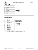
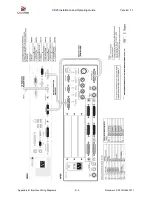
TIMECODE - DB9M
TIMECODE – DB9M
Pin Description
1
TIMECODE SIGNAL - Projector 1
2
TIMECODE SIGNAL - Projector 2*
3 N/C
4 N/C
5
+5VDC @ 250mA OUT
6 GND
7 GND
8 GND
9
LED DRIVE SIGNAL TO TCRH
(“Timecode Valid“– active low)
Note:
Pin 2 is only connected if a second projector is used (with a Y cable)
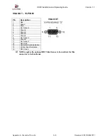
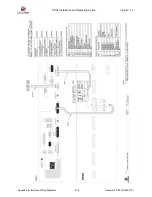
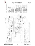
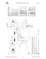
DIGITAL VIDEO INTERFACE PIN-OUT – DVI29F
DIGITAL VIDEO INTERFACE – DVI29F
Pin Description
1 TMDS
Data2-
2 TMDS
Data2+
3
TMDS Data2/4 Shield
4
5
6
DDC Clock [SCL]
7
DDC Data [SDA]
8
9 TMDS
Data1-
10 TMDS
Data1+
11
TMDS Data1/3 Shield
12
13
14
+5 V Power
15
Ground (for +5 V)
16
Hot Plug Defect
17 TMDS
Data0-
18 TMDS
Data0+
19
TMDS Data0/5 Shield
20
21
22
TMDS Clock Shield
23 TMDS
Clock+
24 TMDS
Clock-
25
DIGITAL VIDEO INTERFACE
29-PIN FEMALE
26
27
28
29
C1
C2
C3
C4
C5
Analog GND Return: (analog R, G, B)
XD20 requires the optional HD Video license to be enabled, for this
connector to be functional.


