


XD20 Installation and Operating Guide
Version 1.1
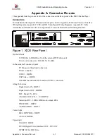
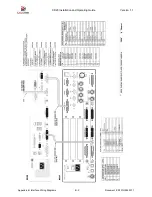
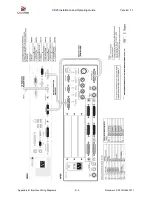
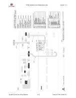
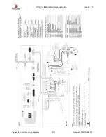
Appendix A. Connector Pin-outs
A-6
Document #: 9301H264001.1
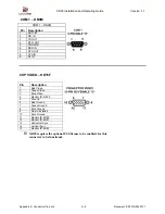
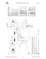
COM 1 – DB9M
COM 1 – DB9M
Pin Description
1
DCD IN
2
RD IN
3 TD
OUT
4 DTR
OUT
5 SIG
GND
6 DSR
IN
7 RTS
OUT
8 CTS
IN
9
RI IN
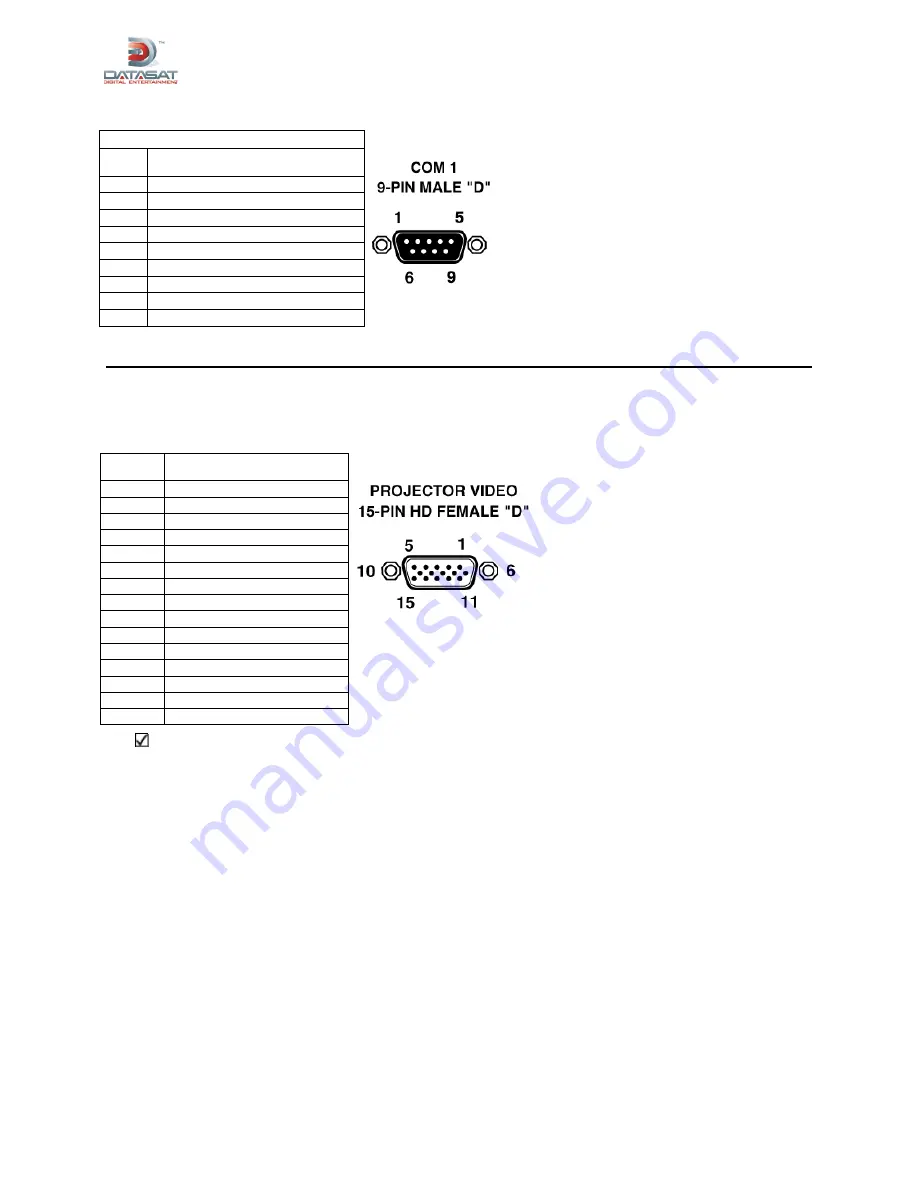
CSP VIDEO – HD15F
XD20 requires the optional CSS license to be enabled, for this
connector to be functional.
Pin
Description
1 Red
Video
2 Green
Video
3 Blue
Video
4
Monitor ID, Bit #2
5 Ground
6 Red
Ground
7 Green
Ground
8 Blue
Ground
9
No pin installed
10 Sync
Ground
11
Monitor ID Bit #0
12
Monitor ID Bit #1
13 Horizontal
Sync
14 Vertical
Sync
15
Monitor ID Bit #3