Chapter 7
7-44
F-7-119
7.10.17.3 When Replacing the Potential Sensor/Potential
Control PCB
0011-8746
iR7105 / iR7095 / iR7086
The machine remains powered after the main power switch is turned off as
long as the power plug is connected to the power outlet. Be sure to discon-
nect the power plug from the power outlet.
1) Turn off the power.
2) Remove the developing assembly, and slide out the process unit.
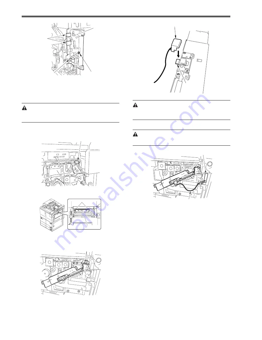
3) Disconnect the connector [1] of the potential sensor.
F-7-120
4) Remove the 2 screws [1], and detach the potential sensor support plate [2].
F-7-121
5) Put back the developing assembly and the process unit.
6) Connect the connector [1] of the potential sensor.
F-7-122
7) Fit the potential checker electrode (FY9-3041) [2] to the potential sensor
[1].
F-7-123
When fitting the checker electrode to the potential sensor, make sure that the
magnet of the checker electrode will not come into contact with the potential
sensor cover.
8) Connect the cable [1] of the potential sensor checker electrode to the
frame assembly (GND) [2] of the machine.
Never bring the clip into contact with the sensor cover. Be sure to fit it fully
away from the sensor window.
F-7-124
9) Fit the door switch actuator to the door switch assembly [1] and the laser
shutter assembly [2].
10) Turn on the powor.
11) Execute the following service mode items:
COPIER > FUNCTION > DPC > OFST
12) Record the value of <OFST> on the service sheet.
13) Turn off the main power switch.
14) Detach the potential sensor checker electrode.
15) Put back the potential sensor support plate.
16) Turn on the power.
7.10.18 Dust-Collecting Roller
7.10.18.1 Removing the Dust-Collecting Roller
0010-8885
iR7105 / iR7095 / iR7086
1) Remove the pre-transfer charging assembly.
2) Remove the two screws [1], and detach the motor cover [2].
[3]
[2]
[1]
[1]
[1]
[2]
[1]
[1]
[1]
[2]
[1]
[2]
Summary of Contents for iR7086
Page 1: ...Sep 7 2007 Service Manual iR7105 7095 7086 Series...
Page 2: ......
Page 6: ......
Page 26: ...Contents...
Page 27: ...Chapter 1 Introduction...
Page 28: ......
Page 30: ......
Page 32: ...Chapter 1 1 2 Not all products are necessarily available in all sales areas...
Page 55: ...Chapter 2 Installation...
Page 56: ......
Page 150: ......
Page 151: ...Chapter 3 Basic Operation...
Page 152: ......
Page 154: ......
Page 159: ...Chapter 4 Main Controller...
Page 160: ......
Page 162: ......
Page 183: ...Chapter 5 Original Exposure System...
Page 184: ......
Page 228: ......
Page 229: ...Chapter 6 Laser Exposure...
Page 230: ......
Page 232: ......
Page 238: ...Chapter 6 6 6 F 6 7 1 Laser light 2 Laser shutter 1 2 1 2 2 1...
Page 240: ......
Page 241: ...Chapter 7 Image Formation...
Page 242: ......
Page 246: ......
Page 294: ......
Page 295: ...Chapter 8 Pickup Feeding System...
Page 296: ......
Page 300: ......
Page 353: ...Chapter 9 Fixing System...
Page 354: ......
Page 378: ......
Page 379: ...Chapter 10 External and Controls...
Page 380: ......
Page 384: ......
Page 394: ...Chapter 10 10 10 F 10 7...
Page 417: ...Chapter 11 MEAP...
Page 418: ......
Page 420: ......
Page 466: ......
Page 467: ...Chapter 12 RDS...
Page 468: ......
Page 470: ......
Page 479: ...Chapter 13 Maintenance and Inspection...
Page 480: ......
Page 482: ......
Page 496: ......
Page 497: ...Chapter 14 Standards and Adjustments...
Page 498: ......
Page 526: ......
Page 527: ...Chapter 15 Correcting Faulty Images...
Page 528: ......
Page 530: ......
Page 560: ......
Page 561: ...Chapter 16 Self Diagnosis...
Page 562: ......
Page 564: ......
Page 584: ......
Page 585: ...Chapter 17 Service Mode...
Page 586: ......
Page 588: ...Contents 17 8 1 1 COPIER Items 17 94...
Page 688: ......
Page 689: ...Chapter 18 Upgrading...
Page 690: ......
Page 692: ......
Page 696: ...Chapter 18 18 4...
Page 713: ...Chapter 18 18 22 formatting and download the system software once again...
Page 726: ...Chapter 19 Service Tools...
Page 727: ......
Page 729: ......
Page 733: ......
Page 734: ...Sep 7 2007...
Page 735: ......


