2
2
2-15
2-15
Technical Explanation > Main Controller > Security Function (Encryption Key, Certificate and Protection of Password) > Security Information Structure
Technical Explanation > Main Controller > Security Function (Encryption Key, Certificate and Protection of Password) > Security Information Structure
Security Function (Encryption Key, Certificate and
Protection of Password)
■
Overview
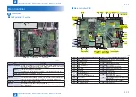
A PCB called "TPM PCB" is installed on the machine's Main Controller PCB. TPM, which
is an abbreviation for "Trusted Platform Module", is a name of a chip that has a function for
generating and saving the encryption key as well as public-key encryption arithmetic function.
The TPM PCB protects security information (passwords, certificates and encryption keys)
stored in the Flash. It does not protect the setting/registered/saved data other than security
information.
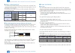
Encryption and decryption of security information use the TPM key within the chip.
Memory area
TPM Chip
Root Key
TPM Key
Public Key Pair for
SSL Communication
Data Storing Key
Password
Encryption Key
User Certificate
Since the TPM key is safely
stored using the root key in
the TPM chip, high security
is maintained.
All information is encrypted and stored by the
TPM key which was encrypted by root key.
User Certificate
Data Storing Key
Public Key Pair for
SSL Communication
Password
Encryption Key
TPM Chip
Memory area
As it is practically impossible to extract the TPM key from the chip, the machine's security
information is well protected even when the following cases occur:
• If the hard disk or the Main Controller PCB is removed and installed in another MFP (as the
TPM PCB retains the model information when the TPM setting is enabled)
• If the machine's system is intruded upon via the network
The setting is required in Settings/Registration mode.
Management Settings > Data Management > TPM Settings > On (default: Off)
F-2-21
■
Security Information Structure
The operation of the security function differs depending on the TPM settings on the UI.
There are 2 types of TPM settings, and the respective flows of security information are
described below:
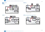
Image diagram when the TPM settings are enabled
TPM PCB
TPM Key
Backup Key
for TPM failure
Public Key
Common
Key
Password
Flash PCB
USB flash drive
Password
(Temporarily
stored in Flash)
When TPM settings are enabled, the TPM key becomes valid, so three-stage keys can be
used. Therefore, the security information of each machine is securely protected.
The security information for this setting consists of three keys and the information of multiple
passwords stored in the Flash PCB.
Each piece of information is stored in the specified storage location. (enclosed in blue in the
above diagram)
As this information is linked to the security information in the lower layer, the function does
not work unless all information is available.
Note that, as a backup function in the case of failure, a backup key is temporarily stored in
the Flash memory. (Limited to the first time when TPM Settings is turned to On)
This key can be backed up using a USB flash drive. After being backed up, it is deleted from
the Flash PCB.
As the stored public key information is lost upon failure/replacement of the Flash PCB, the
security information cannot be correctly decoded. In this case, "Initialize All Data/Settings" of
Settings/Registration needs to be executed to disable TPM settings.
F-2-22

